
Fuel cell with removable/replaceable cartridge and method of making and using the fuel cell and cartridge

Inactive Publication Date: 2005-10-20
MORE ENERGY
View PDF16 Cites 20 Cited by
  • Summary
  • Abstract
  • Description
  • Claims
  • Application Information

AI Technical Summary

Benefits of technology

[0015] The valve system may comprise a first part which is coupled to the fuel cell and a second part which is coupled to the cartridge. The second part may be insertable into the first part. The second part may be releasably connectable to the first part. When the second part is disconnected from the first part, the first part may prevent fluid from exiting out of the fuel cell and the second part prevents fluid from exiting out of the cartridge. When the second part is disconnected from the first part, the first part may prevent fluid from leaking out of the fuel cell and the second part prevents fluid from leaking out of the cartridge.
[0055] The method may further comprise forcing fuel to enter into the at least one variable volume fuel chamber of the cartridge from the at least one variable volume fuel chamber of the fuel cell, forcing electrolyte to enter into the at least one variable volume electrolyte chamber of the cartridge from the at least one electrolyte chamber of the fuel cell, disconnecting the second valve from the first valve, and preventing, with the second valve, spent fuel and electrolyte from exiting the cartridge.

Problems solved by technology

There are a lot of well-known problems with conventional fuel (H2, CH3OH) storage and transportation associated with fuel cells, especially in the field of portable fuels and fuel cells.
As the fuel cell produces electricity, the liquid fuel and the electrolyte in a refillable liquid fuel cell are gradually exhausted of their useful components.
This process is not easily and / or economically accomplished.
Refilling the fuel cell also presents other difficulties due to the hazardous nature of the spent liquid fuel and the spent electrolyte.

Method used


Image

  • Fuel cell with removable/replaceable cartridge and method of making and using the fuel cell and cartridge
  • Fuel cell with removable/replaceable cartridge and method of making and using the fuel cell and cartridge
  • Fuel cell with removable/replaceable cartridge and method of making and using the fuel cell and cartridge

Examples


Embodiment Construction

[0084] The particulars shown herein are by way of example and for purposes of illustrative discussion of the embodiments of the present invention only and are presented in the cause of providing what is believed to be the most useful and readily understood description of the principles and conceptual aspects of the present invention. In this regard, no attempt is made to show structural details of the present invention in more detail than is necessary for the fundamental understanding of the present invention, the description taken with the drawings making apparent to those skilled in the art how the several forms of the present invention may be embodied in practice.

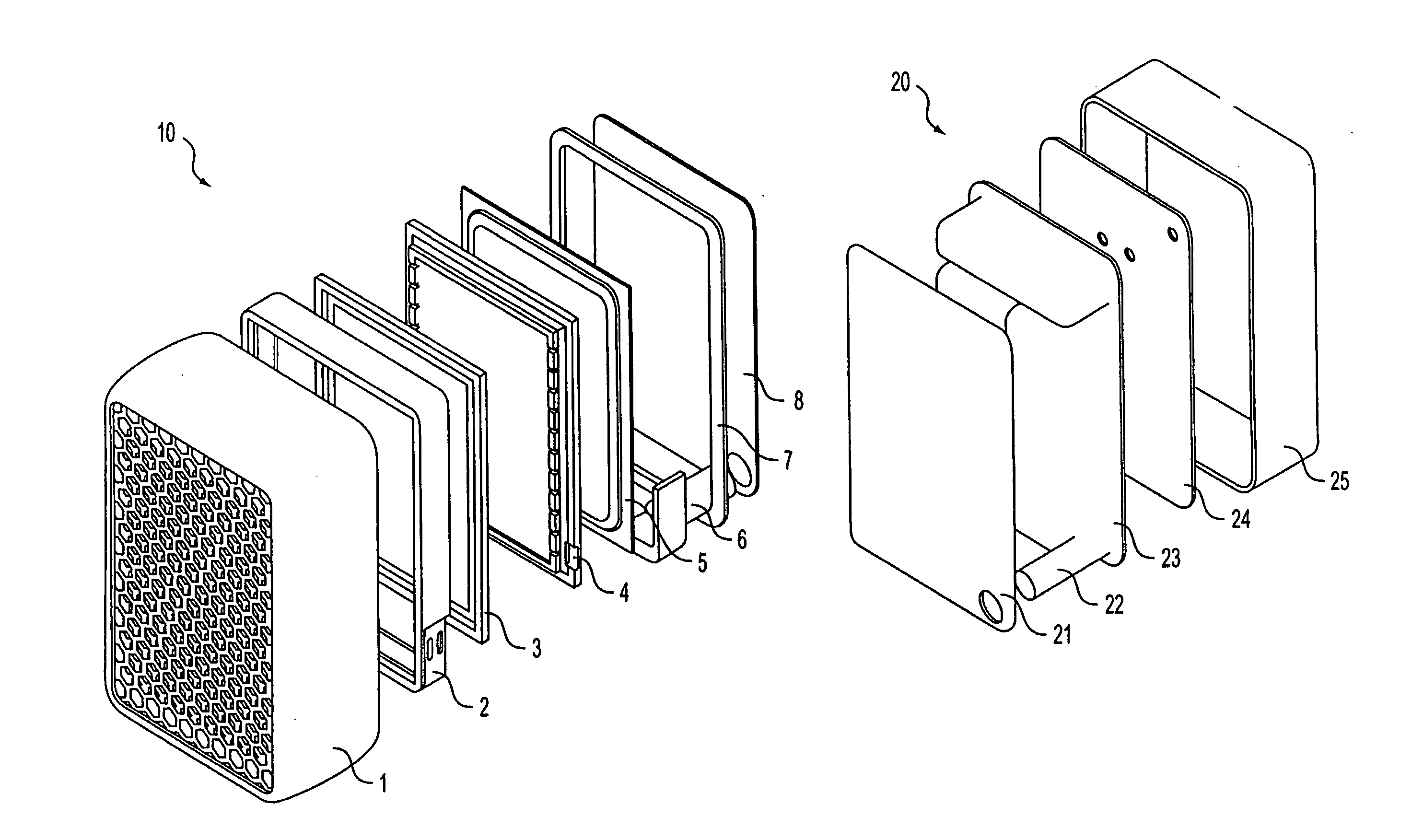
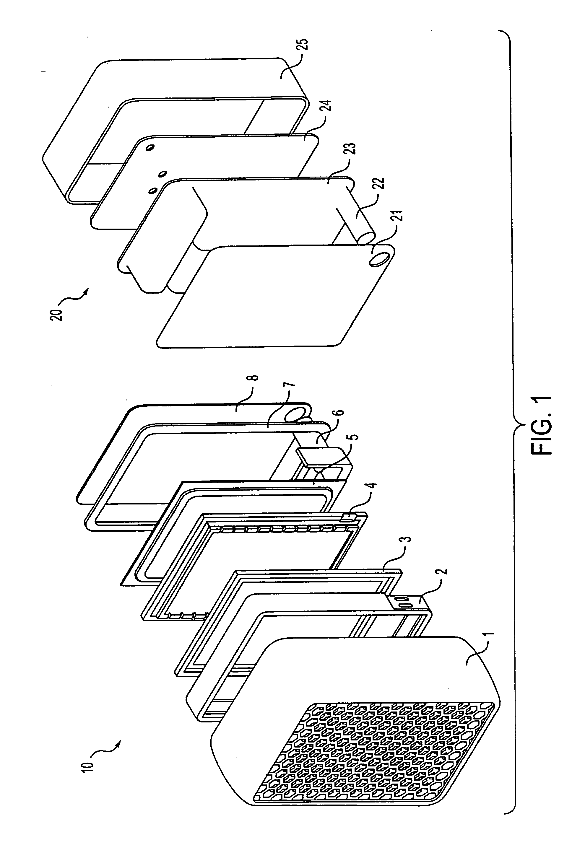
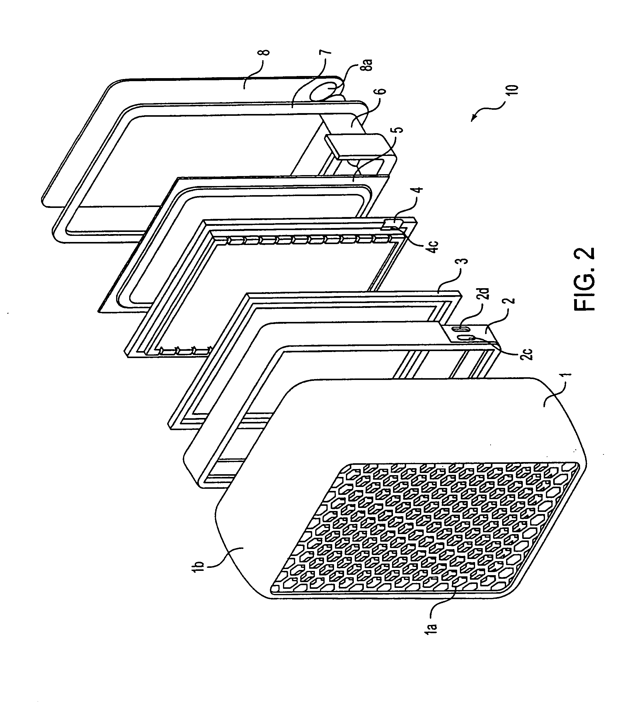
[0085]FIGS. 1-15 show a first non-limiting embodiment of a fuel cell 10 and cartridge 20 arrangement and / or system. The fuel cell 10 includes a front cover 1 and is generally rectangular in shape. Of course, the fuel cell 10 can have any other desired shape including, but not limited to any other polygonal or any other ...


PUM


Abstract

System for refilling a fuel cell wherein the system includes a fuel cell having at least one variable volume chamber, a cartridge having at least one variable volume chamber, and a valve system which regulates or controls fluid flow between the cartridge and fuel cell and vice versa. A method of refilling a fuel cell provides for connecting the cartridge to the fuel cell and transferring fuel and electrolyte from the cartridge to the fuel cell. This Abstract is not intended to define the invention disclosed in the specification, nor intended to limit the scope of the invention in any way.

Description

BACKGROUND OF THE INVENTION [0001] 1. Field of the Invention [0002] The present invention relates to a refillable liquid fuel cell. The invention also relates to a refilling device, e.g., a cartridge, for refilling a fuel cell which is connected to the fuel cell during its use. The present invention also relates to the combination of a fuel cell having one or more compartments for the electrodes and a cartridge having one or more liquid chambers which supplies and stores liquids for the fuel cell. The cartridge is capable of supplying fresh liquids to the fuel cell and also capable of removing the spent liquids from the fuel cell and storing them. [0003] The invention also relates to a fuel cell having a flexible collapsing chamber and a cartridge having a flexible collapsing chamber, wherein the cartridge can be removed from and / or disconnected from the fuel cell as well as a method of making and using these devices. [0004] The invention further relates to a fuel cell and cartridge...

Claims


Application Information

Patent Timeline
IPC IPC(8): B65D6/00H01M2/02H01M8/04H01M8/24
CPCH01M8/04283Y02E60/50H01M8/245Y02P70/50
Inventor FINKELSHTAIN, GENNADIESTRIN, MARKMERON, MOTITORGEMAN, ERIC
Owner MORE ENERGY
Learn More