Hydraulically driven vibrating massagers

a vibrating, hydrostatic technology, applied in the field of massagers, can solve the problems of limiting the range of motion that is possible for the user or users, no prior art dildo is known which can accurately, and the device in u.s. pat. no. 4,790,296 is not convenien

Inactive Publication Date: 2005-10-20
FAULKNER ROGER W +1
View PDF4 Cites 55 Cited by
  • Summary
  • Abstract
  • Description
  • Claims
  • Application Information

AI Technical Summary

Problems solved by technology

No prior art dildo is known which can accurately simulate the feel of an ejaculation to the sexual partner of the one ejaculating, though several attempts have been made.
However, the device in U.S. Pat. No. 4,790,296 is not convenient, in that the rigid stimulator arm limits the range of motions that are possible for the user or users.
The device in U.S. Pat. No. 4,790,296 seriously limits sexual motions, and tends to decrease sexual innovation.
U.S. Pat. No. 5,725,473 describes “a sexual aid including a housing, mounted on detachable legs and containing a motor that urges a dildo, including vibration means, to describe an arcuate path generally coincident with an orifice, such as a vagina.” This device is cumbersome, in that it is not possible for one sexual participant to use the stimulator while simultaneously and flexibly interacting with a sexual partner.
The devices of U.S. Pat. No. 5,725,473 are only minimally useful in sex between partners any time at least one of those partners is a male.
This patent does not disclose or anticipate the use of rapid variations of inflation pressure as a means of causing vibrations.
This patent does not disclose or anticipate the use of the flexible-walled dildo in conjunction with a hydraulic actuator to form a sexual stimulator.
This patent does not disclose or anticipate the actuation of said slidable mechanism by a hydraulic actuator to form an externally driven sexual stimulator.
This patent does not disclose or anticipate the use of liquid for inflating said bladder, nor does it anticipate rapid changes of inflation pressure being used to generate exciting motions or vibrations of the dildo.
This patent does not disclose or anticipate the use of bladders with walls of intentionally inconsistent modulus, nor does it anticipate the use of hydraulic pressure to change the shape of a stimulating device in a directed fashion.
In addition, this patent does not disclose or anticipate the use of use of a hydraulic driver to generate intentional vibrations.
This patent does not disclose or anticipate the use of bladders or tubes with walls of intentionally inconsistent modulus, nor does it anticipate the use of hydraulic pressure to change the shape of a stimulating device in a directed fashion.
In addition, while Stoughton describes the ability of a hydraulic stimulator to deliver stimulation which has its amplitude controlled independently of its frequency, the method described therein contains fundamental limitations with respect to amplitude, frequency, controllability and wave-shape.
That patent does not disclose or anticipate the use of time varying pressure to create vibrations in a fluid filled sac.
In addition, that patent does not disclose or anticipate the use of heat or cold as an adjunct to erotic stimulation in vibrators or other related stimulators.

Method used


Image

  • Hydraulically driven vibrating massagers
  • Hydraulically driven vibrating massagers
  • Hydraulically driven vibrating massagers

Examples


example 1

Variable Wall-Thickness Elastomeric Hydraulic Appliance

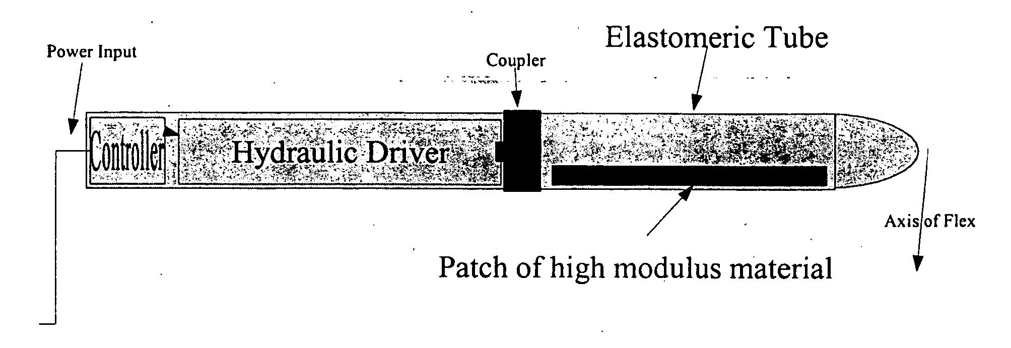
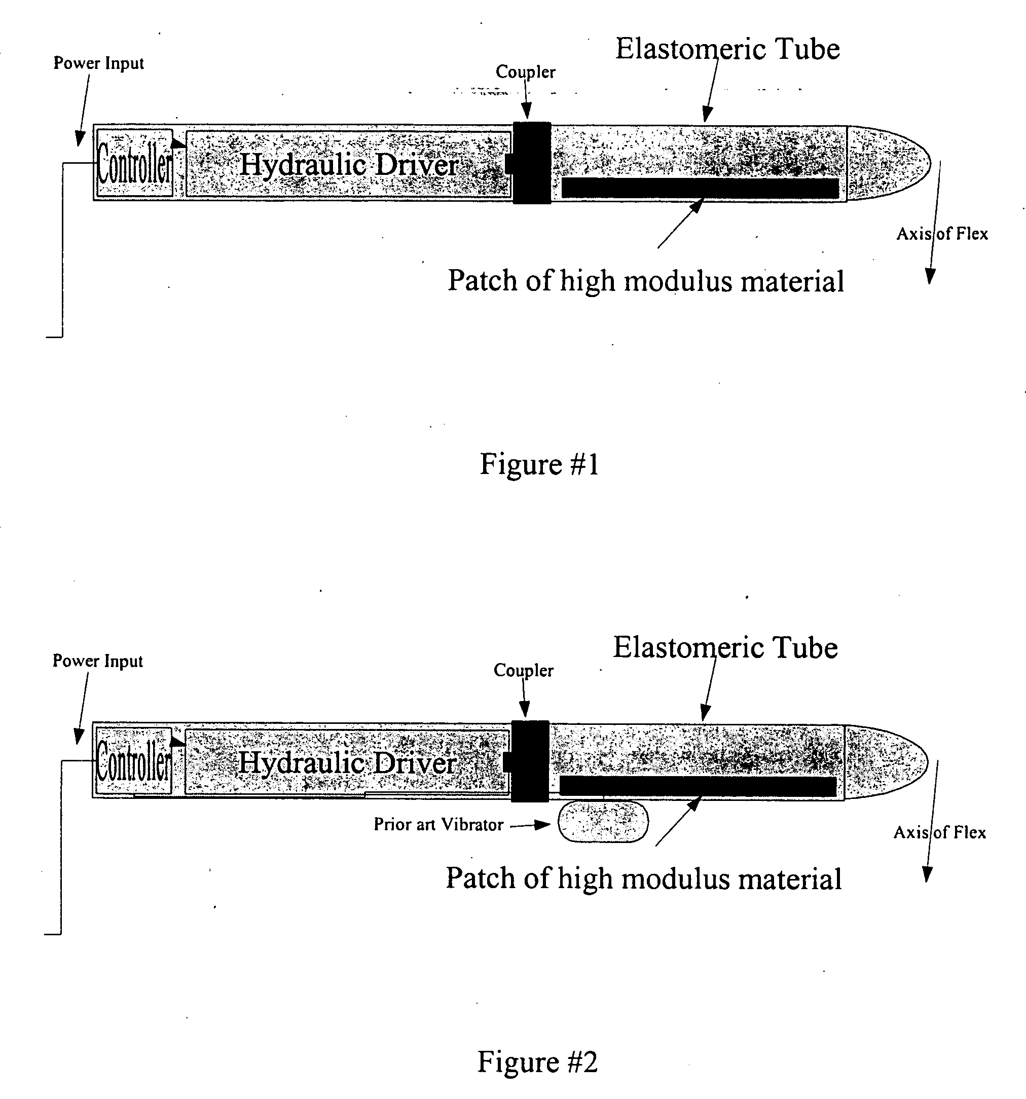
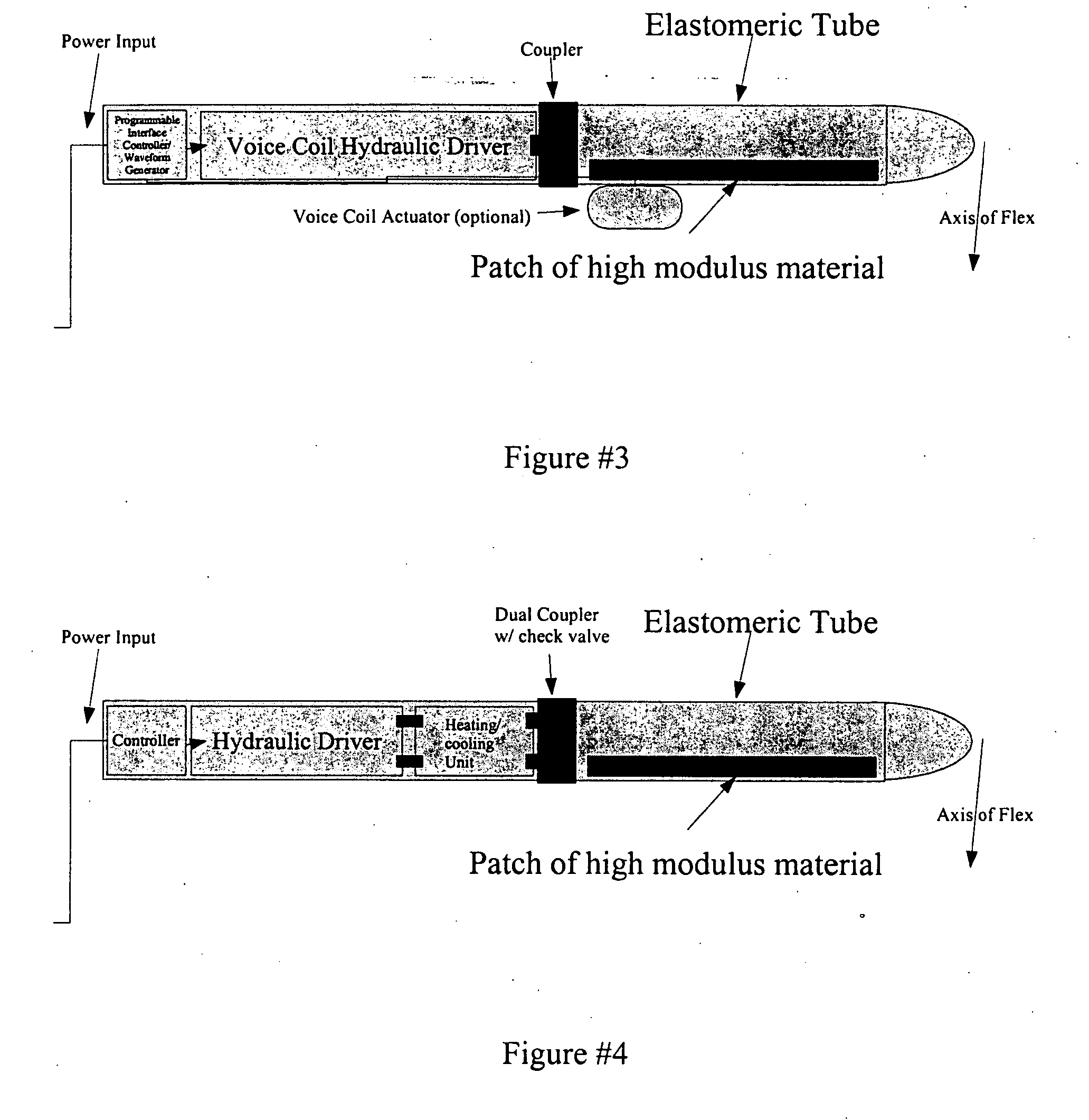
[0064] The appliance in this example is similar to that of U.S. Pat. No. 4,167,938, but has a wall of varying thickness. When inflated, the thinner parts of the wall protrude during the high-pressure phase of the hydraulic pressure cycle. If thin walled areas are radially asymmetrical, the appliance will bend and wiggle during the hydraulic pressure cycle.

example 2

Radially Restricted Elastomeric Hydraulic Appliance

[0065] The appliance of this example has an elastomeric wall which contains radially oriented fibers and / or rigid rings. The fibers and / or rigid rings restrict radial and not axial expansion. Therefore, during the hydraulic cycle the appliance elongates, but does not enlarge radially to any significant extent.

example 3

Helically Restricted Elastomeric Hydraulic Appliance

[0066] The appliance of this example has an elastomeric wall containing helically oriented fibers. During the hydraulic cycle this appliance twists in a manner consistent with the uncoiling action of the fiber helix.


PUM


Abstract

Hydraulically-driven vibrating massagers. Devices for massage and/or sexual stimulation are vibrated and/or rhythmically deformed. The devices have at least two, and normally three elements as follows: (1) One or more hydraulically driven sacs or tubes within a massage and/or sexual stimulation device which are constructed with walls of intentionally varying modulus; (2) A hydraulic actuator to move hydraulic fluid into and out of the device (1) (3) Optionally, a flexible hose or hoses connected at one end to the sexual stimulation device or devices and at the other end to the hydraulic actuator. The particular devices actuated by the present invention can include various prior art massage and/or sexual stimulation devices, including muscle massagers, dildos, and penis rings (with or without attachment to secondary anal stimulators), sexually stimulating underwear, and two-ended dildos intended to anchor on one end in a vagina and/or anus, for example. For purposes of this disclosure, “sexually stimulating devices” and other similar language should also be understood to include massage devices that are not specifically intended for sexual stimulation. Compared to prior art vibrating sexual stimulators, the devices of this invention are capable of more complex modes of motion and both higher amplitude and slower deformation rates. The hydraulically actuated sexual stimulators of this invention are powerful, compact, quiet, and have low rates of heat generation compared to prior art electrically-driven vibrating sexual stimulation devices. In addition, the devices can be conveniently heated or cooled via the hydraulic fluid.

Description

CROSS REFERENCE TO RELATED APPLICATIONS [0001] This application is a continuation in part of application Ser. No. 10 / 925,552, filed on Aug. 25, 2004, and claims priority of Provisional application Ser. No. 60 / 497,385, filed on Aug. 25, 2003.FIELD OF THE INVENTION [0002] This invention relates to massagers, more particularly to erotic stimulators. BACKGROUND OF THE INVENTION [0003] The human penis becomes and remains erect by hydraulic pressure. Therefore it is useful to consider some hydraulic characteristics of the penis as a sort of prior art dildo. A review of the workings of the penis is contained in the August, 2000 issue of Scientific American, in an article by Irwin Goldstein on “Male Sexual Circuitry.” During erection the muscles in the penis artery walls relax, allowing blood to flood in to the porous sinus-like tissue. The penis inflates to a pressure nearly equal to the systolic (arterial) blood pressure of the male, as the porous sinus-like tissue of the penis inflates w...

Claims


Application Information

Patent Timeline
Patent Type & Authority Applications(United States)
IPC IPC(8): A61H19/00A61H23/04
CPCA61H19/00A61H19/34A61H19/44A61H19/50A61H23/04A61H19/32A61H2205/085A61H23/0254A61H2201/1619A61H2205/082A61H2205/086A61H2201/0103
Inventor FAULKNER, ROGER W.RICHER, JACQUES P.
Owner FAULKNER ROGER W
Why Eureka
Try Eureka