Fluid delivery system, fluid path set, sterile connector and improved drip chamber and pressure isolation mechanism

a technology of fluid delivery system and drip chamber, which is applied in the direction of instruments, catheters, process and machine control, etc., can solve the problems of less than optimal injection bolus, requiring operator effort, and reducing the fluid pressure in the syringe.

Inactive Publication Date: 2005-10-20
BAYER HEALTHCARE LLC
View PDF26 Cites 179 Cited by
  • Summary
  • Abstract
  • Description
  • Claims
  • Application Information

AI Technical Summary

Benefits of technology

[0020] In one aspect, the manual control includes a first actuator providing control of flow rate of the first fluid by changing the force on the first actuator and a second actuator, the second actuator causing the injector to enter into a preprogrammed high pressure injection mode when placed in an on state. The system may further include a pressure sensor in fluid communication with the second fluid path via a pressure-activated isolator that isolates the pressure sensor from pressures in the second fluid path above a set pressure. In one embodiment, the per-patient disposable section may include a check valve in the second fluid path separating components of the per-patient disposable section from the multi-patient reusable section to reduce or eliminate flow of contaminated fluid into the multi-patient reusable section.
[0076] Furthermore, the pump device may be a syringe, and the method may include actuating the fluid control device to isolate the syringe from the source of injection fluid and the patient, and retracting a syringe plunger in the syringe to reduce fluid pressure in the syringe.

Problems solved by technology

Manual sources of fluid pressure and flow used in medical applications such as syringes and manifolds thus typically require operator effort that provides feedback of the fluid pressure / flow generated to the operator.
The feedback is desirable, but the operator effort often leads to fatigue.
However, compliance in the system components, for example, expansion of the syringe, tubing, and other components under pressure, using such a manifold system can lead to a less than optimal injection bolus.
Moreover, the arrangement of the system components of U.S. Pat. No. 5,800,397 results in relatively large amounts of wasted contrast and / or undesirable injection of an excessive amount of contrast when the low pressure, typical saline system, is used.
Unlike manual injection systems, however, there is little if any feedback to the operator of system pressure in the systems disclosed in the U.S. Patents identified previously.

Method used


Image

  • Fluid delivery system, fluid path set, sterile connector and improved drip chamber and pressure isolation mechanism
  • Fluid delivery system, fluid path set, sterile connector and improved drip chamber and pressure isolation mechanism
  • Fluid delivery system, fluid path set, sterile connector and improved drip chamber and pressure isolation mechanism

Examples


Embodiment Construction

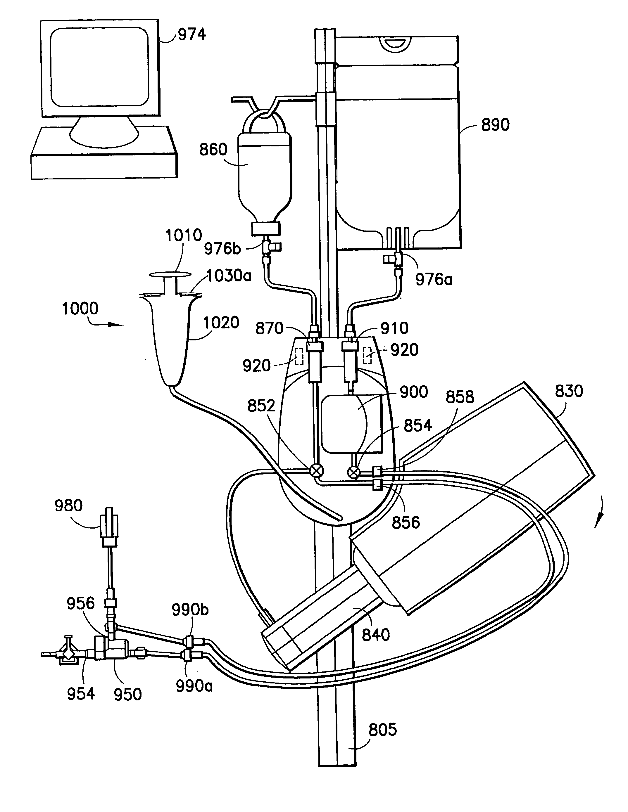
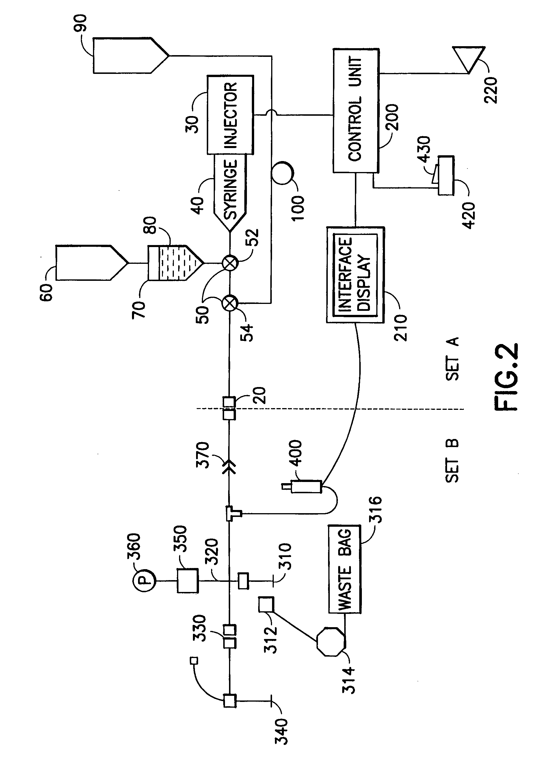
[0121] In one aspect, the present invention provides an energy / signal source to generate fluid pressure / flow while also providing to the user tactile and / or audible feedback of the fluid pressure generated, allowing the user to modulate the fluid pressure / flow. The powered injection system of the present invention is capable of providing, for example, both precise low-flow / low-pressure fluid delivery for powered coronary injections and high-flow / high-pressure fluid delivery for ventricle injections.

[0122]FIG. 2 illustrates one embodiment of the present invention in which injector system 10 is preferably divided into two sections: a multi-patient section or set A and a per-patient disposable section or set B. Section or set A and section or set B are preferably separated and removably coupled into fluid connection by a high-pressure connector or by a high-pressure, “aseptic” connector 20 such as the septum connector disclosed in U.S. Pat. No. 6,096,011, assigned to the assignee of t...


PUM


Abstract

The fluid path set is intended for use in a fluid delivery system. The fluid path set includes a multi-patient use section adapted for connection to a syringe used in the fluid delivery system, and to a source of fluid, such as contrast media, to be loaded into the syringe. The fluid path set further includes a per-patient use section that is removably connected to the multi-patient use section. A connector removably connects the multi-patient use section and the per-patient use section. A drip chamber is provided between the source of fluid and the syringe, and includes a projection for determining a level of fluid in the drip chamber. The per-patient use section includes a pressure isolation mechanism. The pressure isolation mechanism includes a lumen, a pressure isolation port, and a valve member with a biasing portion that biases the valve member to a normally open position.

Description

RELATED APPLICATIONS [0001] This application may contain subject matter that is related to that disclosed in the following co-pending applications: (1) application Ser. No. 10 / 818,748, filed on Apr. 6, 2004; (2) application Ser. No. 10 / ______, filed on Apr. 5, 2004; (3) application Ser. No. 10 / 326,582, filed on Dec. 20, 2002; (4) application Ser. No. 10 / 237,139, filed on Sep. 6, 2002; and (5) application Ser. No. 09 / 982,518, filed on Oct. 18, 2001, the disclosures of which are incorporated herein by reference.BACKGROUND OF THE INVENTION [0002] 1. Field of the Invention [0003] The present invention relates generally to fluid delivery systems for supplying fluids during medical diagnostic and therapeutic procedures, further, to fluid transfer sets and flow controlling and regulating devices associated therewith used with fluid delivery systems for conducting and regulating fluids flows. [0004] 2. Description of Related Art [0005] In many medical diagnostic and therapeutic procedures, ...

Claims


Application Information

Patent Timeline
Patent Type & Authority Applications(United States)
IPC IPC(8): A61M5/00A61M5/14A61M5/145A61M5/168A61M5/36A61M25/16A61M39/24
CPCA61M5/007A61M2205/583A61M5/14546A61M5/16831A61M5/1684A61M5/16881A61M5/365A61M39/24A61M2005/1403A61M2039/242A61M2039/2473A61M2039/2486A61M2039/2493A61M2205/3306A61M2205/581A61M5/1408A61M2005/14553
Inventor SPOHN, MICHAEL A.HAURY, JOHN A.DEDIG, JAMES ALBERTFELIX, SUSAN LYNNMCCOPPIN, ANTHONY S.EHRENBERGER, MICHAEL J.GIMBEL, JAMES M.SUNDAY, JARED A.
Owner BAYER HEALTHCARE LLC
Why Eureka
Try Eureka