
Removeable embolus blood clot filter and filter delivery unit

a technology of embolism and filter, which is applied in the field of removal of embolism blood clot filter and filter delivery unit, can solve the problems of pulmonary embolism risk disappearing, the filter is not easily or safely removed, and the risk of vena cava injury or rupture, etc., and achieves the effect of convenient removal

Inactive Publication Date: 2005-10-20
CR BARD INC
View PDF99 Cites 104 Cited by
  • Summary
  • Abstract
  • Description
  • Claims
  • Application Information

AI Technical Summary

Benefits of technology

[0007] It is a primary object of the present invention to provide a vessel implantable filter of shape memory material having temperature induced austenitic and martensite states which may be easily removed by a single removal device after an extended period of time without significantly injuring the vessel wall.
[0008] Another object of the present invention is to provide a blood clot filter of shape memory material which operates in a temperature induced austenitic state to exert a force on the wall of a vessel by means of oppositely disposed legs to maintain the filter in place, but which may easily be removed after the endothelium layer has covered the ends of the filter legs without significant damage to the vessel wall.
[0010] Yet another object of the present invention is to provide a novel and improved vessel implantable filter having one or more expandable appendages which engage the wall of the vessel. An elastic hook is formed on the free end of an appendage to pierce the vessel wall and insure that the filter does not migrate in response to normal respiratory functions or in the event of a massive pulmonary embolism. The hook is formed to have a maximum migration force, and when subjected to forces below the maximum migration force, the hook retains its shape. When subjected to forces above the maximum migration force, the hook straightens and can be withdrawn without significant damage to the vessel wall.
[0011] A further object of the present invention is to provide a novel and improved vessel implantable filter having a plurality of expandable appendages which engage the wall of a vessel. Three to twelve of such appendages are provided which have an elastic hook formed on the free end of the appendage to pierce the vessel wall and insure that the filter does not migrate when subjected to a pressure gradient falling within a range of from 10 mmHg to 120 mmHg in a 28 mm vessel (filter migration resistance). Each hook is formed to have a maximum migration force, and when subjected to forces below the maximum migration force, the hook retains its shape. When subjected to forces above the maximum migration force, the book straightens and can be withdrawn without significant damage to the vessel wall. The maximum migration force for each hook is dependent upon the desired total filter migration resistance and the number of hooks formed on the filter.

Problems solved by technology

Now any attempt to remove the filter results in a risk of injury to or rupture of the vena cava.
In such cases, patients are often adverse to receiving a permanent implant, for the risk of pulmonary embolism may disappear after a period of several weeks or months.
However, most existing filters are not easily or safely removable after they have remained in place for more than two weeks, and consequently longer term temporary filters which do not result in the likelihood of injury to the vessel wall upon removal are not available.
However, after growth of the endothelium layer the combined inward and longitudinal movement of the filter sections as they are drawn apart can tear this layer.

Method used


Image

  • Removeable embolus blood clot filter and filter delivery unit
  • Removeable embolus blood clot filter and filter delivery unit
  • Removeable embolus blood clot filter and filter delivery unit

Examples


Embodiment Construction

[0024] By forming the body of a blood clot filter of a Nitinol alloy material, such as Nitinol wire, transition between the martensitic and austenitic states of the material can be achieved by temperature transitions above and below a transition temperature or transition temperature range which is at or below body temperature. Such controlled temperature transitions have conventionally been employed to soften and contract the Nitinol filter body to facilitate insertion into a catheter and to subsequently expand and rigidify the body within a vascular or other passageway. Although the filters of the present invention are preferably formed from a temperature responsive shape memory material, such as Nitinol, they can also be formed of a compressible spring metal such as stainless steel or a suitable plastic.

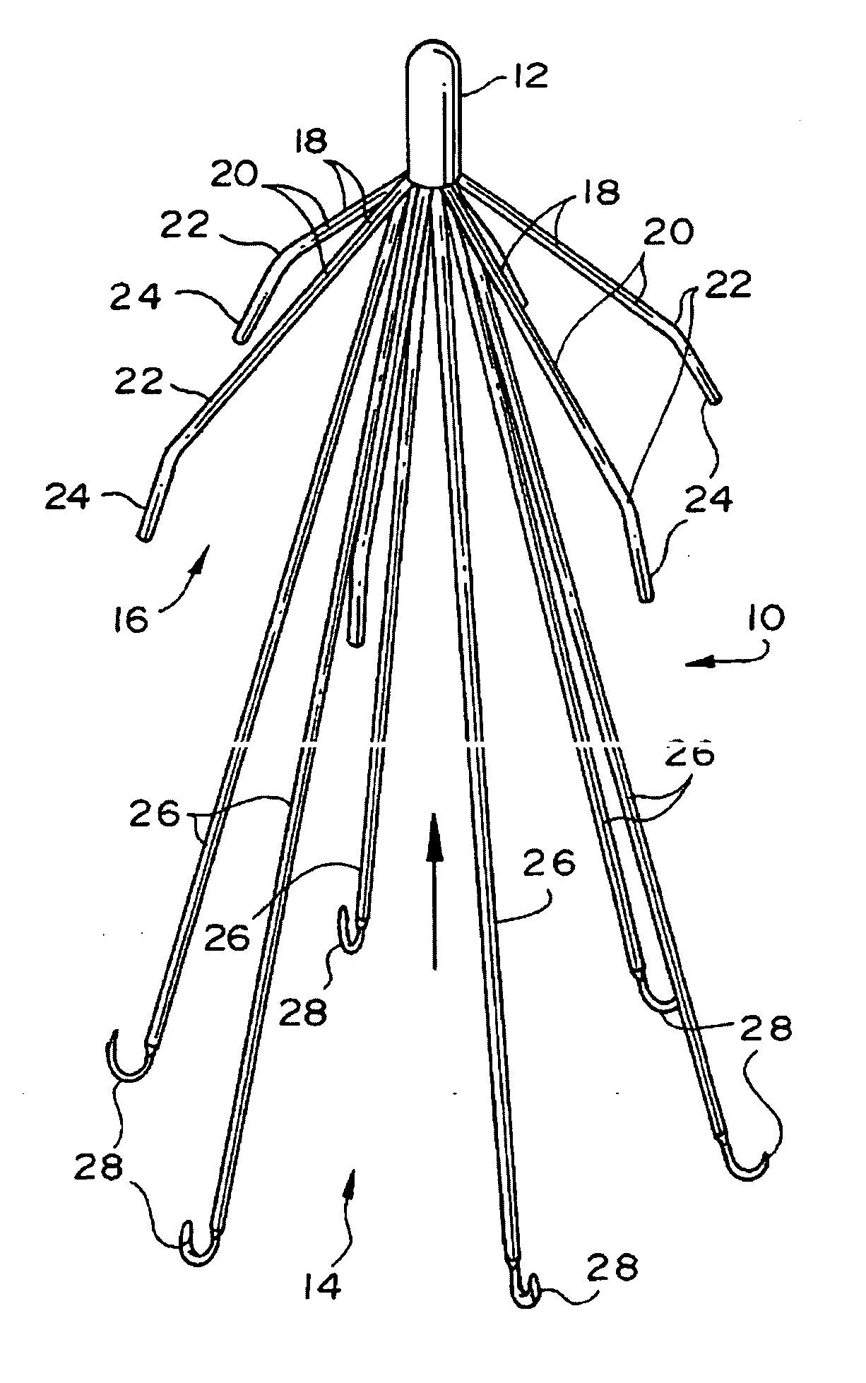
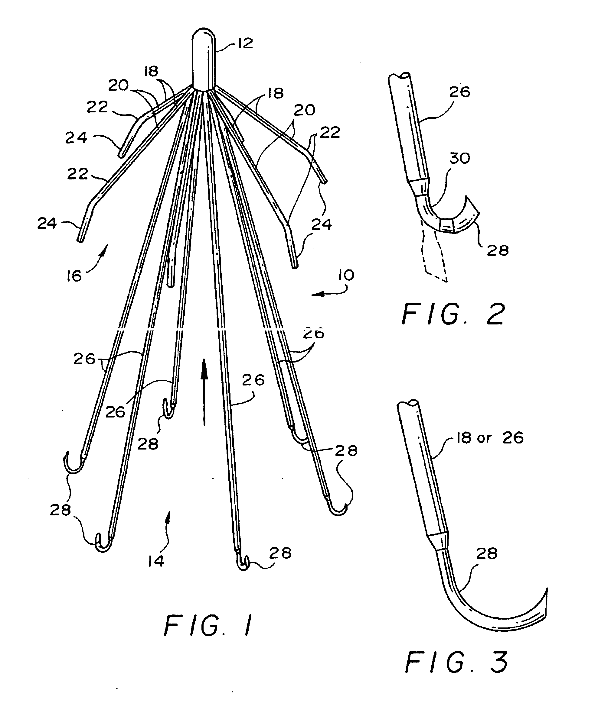
[0025] Referring now to FIG. 1, an expanded blood clot filter 10 is illustrated which is made from sets of elongate metal wires. The wires are held together at the filter trailing...


PUM


Abstract

A blood clot filter which is collapsible toward a central longitudinal axis into a collapsed configuration for insertion into a blood vessel and which is radially expandable outwardly from the longitudinal axis to an expanded configuration for contact with the inner wall of the blood vessel at two longitudinal spaced locations. A first plurality of spaced, elongate arms, in the expanded configuration of the filter, curve outwardly away from the longitudinal axis toward the leading end of the filter to form a first filter basket and to center a hub at the trailing end of the filter within the vessel. A second plurality of spaced elongate legs angle outwardly away from the longitudinal axis toward the leading edge of the filter in the expanded configuration thereof to form a second filter basket opening toward the leading end. The ends of these legs include hooks to bend and straighten in response to withdrawal force.

Description

[0001] This application is a continuation-in-part application of U.S. Ser. No. 09 / 160,384 filed Sep. 25, 1998.BACKGROUND OF THE INVENTION [0002] In recent years, a number of medical devices have been designed which are adapted for compression into a small size to facilitate introduction into a vascular passageway and which are subsequently expandable into contact with the walls of the passageway. These devices, among others, include blood clot filters which expand and are held in position by engagement with the inner wall of a vein. It has been found to be advantageous to form such devices of a shape memory material having a first, relatively pliable low temperature condition and a second, relatively rigid high-temperature condition. By forming such devices of temperature responsive material, the device in a flexible and reduced stress state may be compressed and fit within the bore of a delivery catheter when exposed to a temperature below a predetermined transition temperature, bu...

Claims


Application Information

Patent Timeline
Patent Type & Authority Applications(United States)
IPC IPC(8): A61F2/01A61M29/00
CPCA61F2/01A61F2002/011A61F2230/008A61F2230/005A61F2230/0067A61F2002/016A61F2220/0008A61F2/0103A61F2/0105A61F2/011
Inventor RAVENSCROFT, ADRIAN C.KLESHINSKI, STEPHEN J.
Owner CR BARD INC
Features
  • Generate Ideas
  • Intellectual Property
  • Life Sciences
  • Materials
  • Tech Scout
  • Unparalleled Data Quality
  • Higher Quality Content
  • 60% Fewer Hallucinations
Learn More