Measuring gauge and measuring tool

Inactive Publication Date: 2005-10-27
JOSEPH JERRY
View PDF18 Cites 4 Cited by
  • Summary
  • Abstract
  • Description
  • Claims
  • Application Information

AI Technical Summary

Benefits of technology

[0017] It is another object of the present invention is to provide a measurement gauge easily manufactured from various materials, including a plastic, a metal, an organic substance such as wood, or a combination thereof.
[0040] According to another embodiment of the present invention, there is provided a measuring gauge tool system, wherein: the means for pivotally engaging enables at least one of a planar pivoting and a dihedral pivoting, whereby the measurement gauges may be conveniently stored as a unit and pivotally selectable for a use.

Problems solved by technology

Unfortunately, this design does not allow the remaining gauging members to be used except with an additional step of opening a new member and replacing the previously exposed member.
This design allows a user to quickly try closely related gauge sizes but is not collapsible.
Unfortunately, none of the conventional gauges known includes a broad arrangement of circular-type gauges supporting an array of negative-type measurement gauges bounded by opposing parallel sides having the same measurement as an inner radius.
Furthermore, none of the conventional gauges allows a thin multi-gauge design easily manufactured from a plastic or non-metallic material, that will sit flat in a user's pant or shirt pocket for easy access after combination.
Finally, none of these designs enables both a compact / folding ability while retaining the ability to quickly check associated multiple gauge sizes, for example a size range of 19, 20, 21, 23 mm, without additional finger movements to expose new gauge members.

Method used


Image

  • Measuring gauge and measuring tool
  • Measuring gauge and measuring tool
  • Measuring gauge and measuring tool

Examples


first embodiment

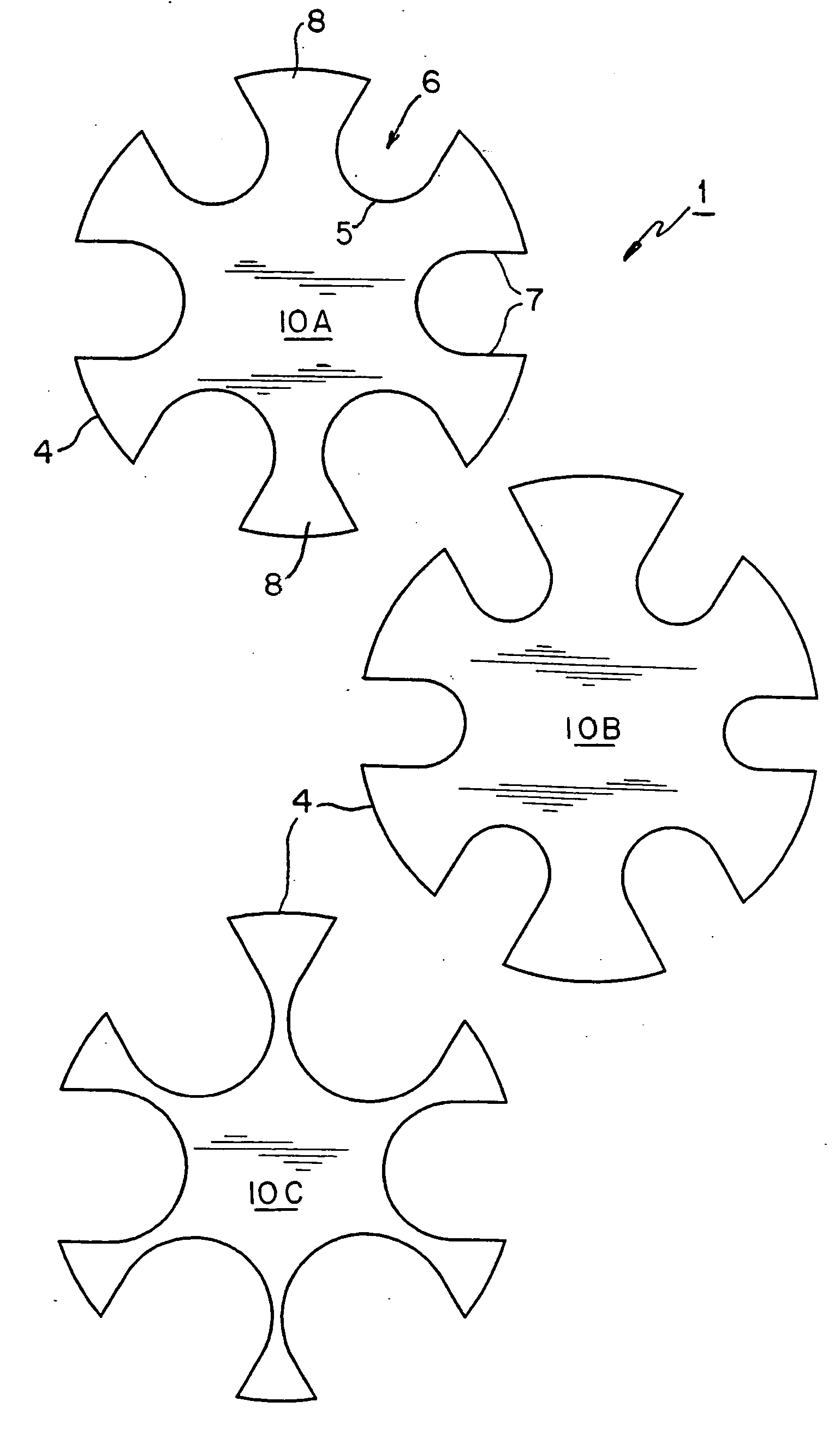
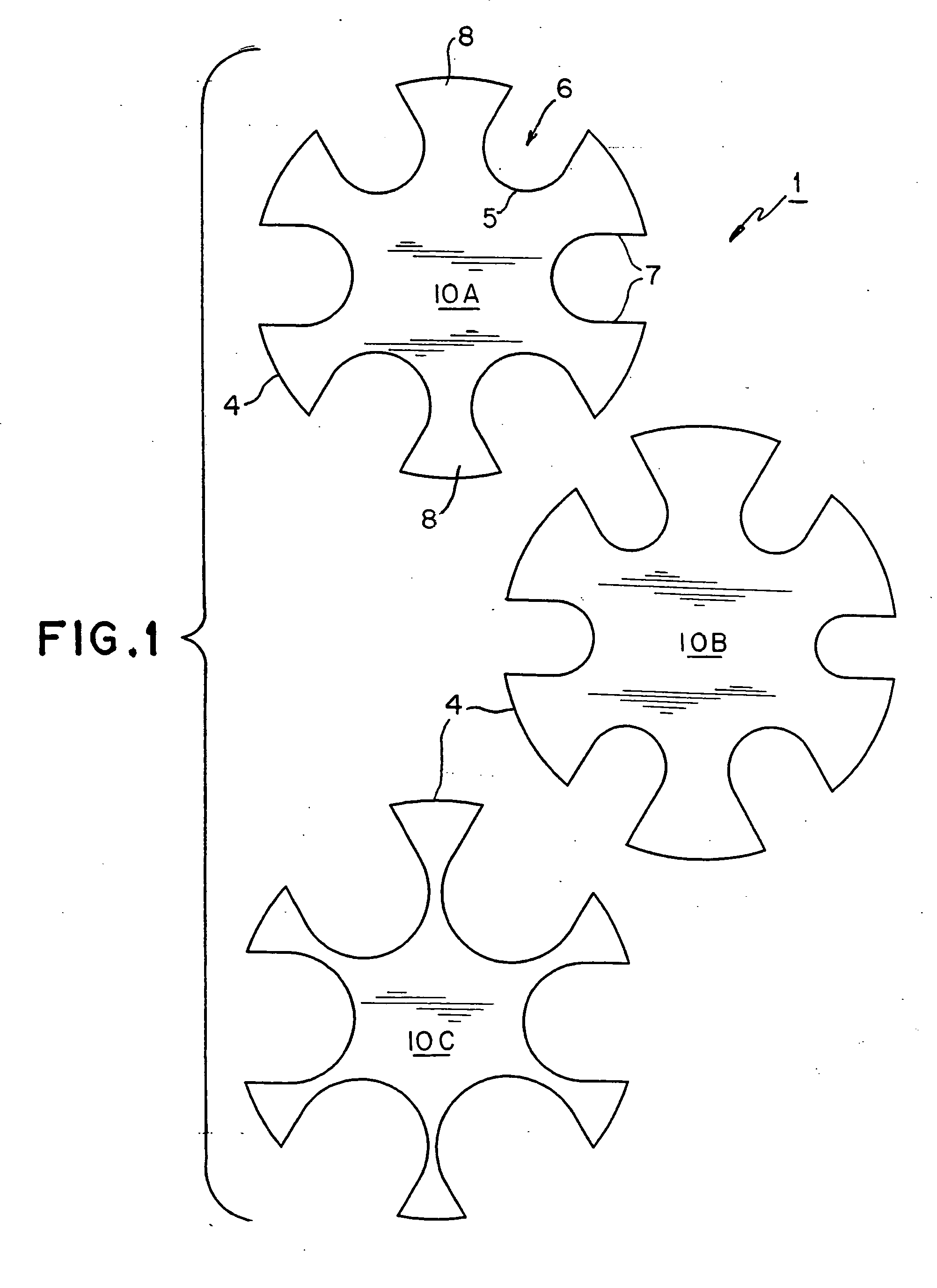
[0061] Referring now to FIG. 1, a measuring gauge tool 1 includes a plurality of individual measuring gauges, or measuring gauge tools. The present embodiment includes a total of three individual measuring gauges, a small size gauge 10A, a middle size gauge 10B, and a large size gauge 10C, but the number of individual gauges may be increased or decreased depending upon a manufacturer's desire. It is specifically noted that measuring gauge tool 1 may include a single measuring having selectively sized openings. One of the preferred embodiments of the present invention includes three measuring gauges, as shown.

[0062] Each gauge 10A, 10B, and 10C includes a plurality of notches 6 and fingers 8 alternatingly spaced about a defined outer boundary or perimeter 4. As shown each gauge is conveniently shown as a generally cylindraceous body having outer boundary or perimeter 4 shaped such that notches 6 and fingers 8 are spaced radially about a common center point. Those skilled in the art w...

embodiment 2

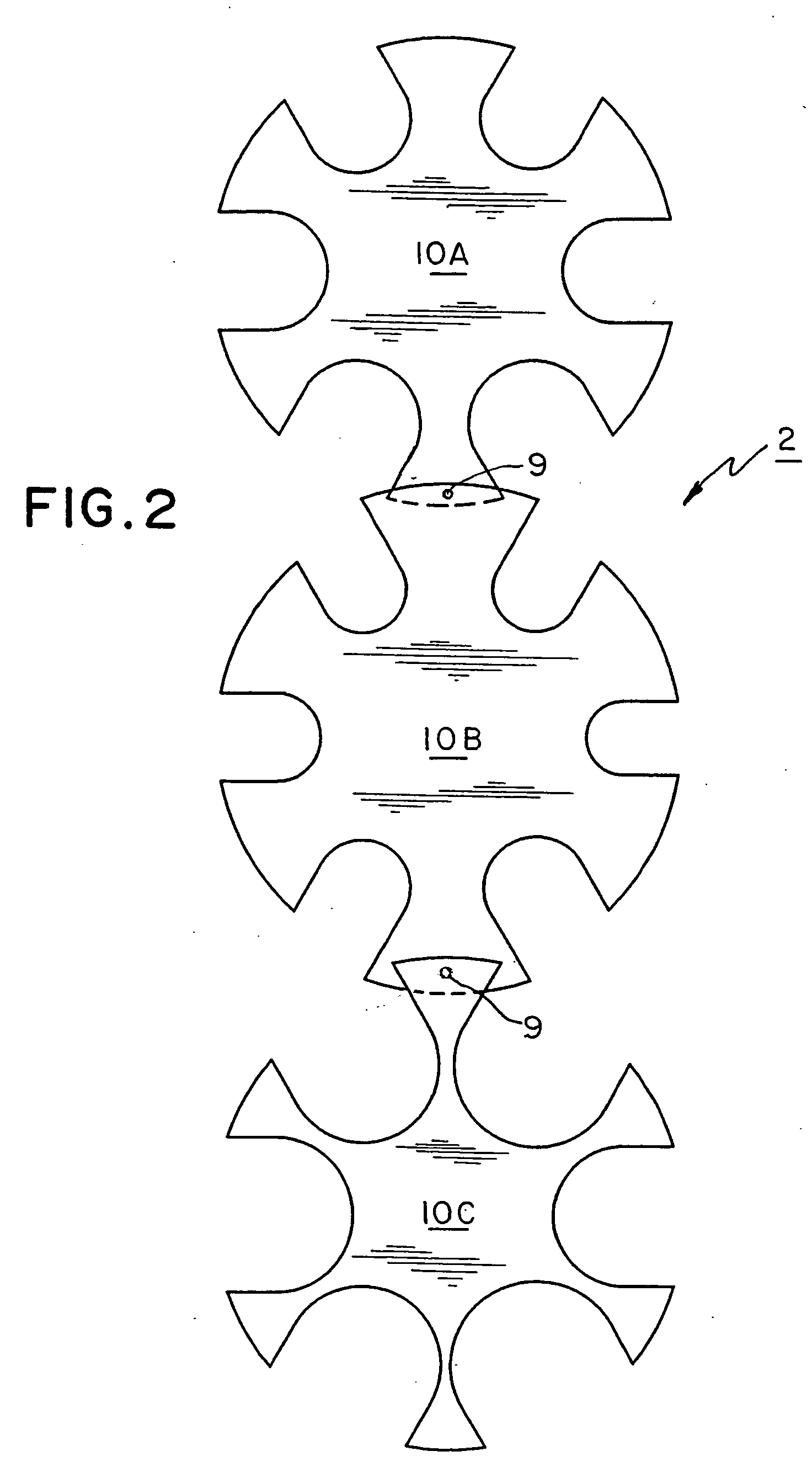
[0065] Referring now to FIGS. 2, 3A, and 3B, individual gauges 10A, 10B, and 10C are co-joined forming a measuring gauge tool 2. The individual measuring gauges 10A, 10B, 10C are pivotably joined proximate respective outer boundaries 4 at respective pivot hinges 9, 9 as shown, to form alternative measuring guide tool embodiment 2. Pivot hinges 9, 9 have respective pivot pins 9A, 9B as shown. It should be understood, that pivot hinges 9, 9 are a pivot hinge means readily adapted to a wide range of types of pivot hinge and style of hinge (e.g. barrel hinge, ball-hinge etc.). The present embodiment shown is a form of “planar pivot,” as defined herein. Planar pivots exist wherein each individual gauge's generally flat surface plane pivots along a direction generally parallel relative to the surface planes of the other individual gauge(s) (via hinges 9). It should be further understood, that the various measuring gauge sizes 10A, 10B, 10C may be employed in various orders, from small to ...


PUM


Abstract

A measuring guide and measuring system includes at least one measuring gauge having at least one notch proximate an outer boundary of the gauge. A pair of opposing walls bound each notch and provide an alignment and measurement guide in use. Alternative embodiment include multiple measuring guides pivotally joined in a set allowing an individual guide to be pivoted for use and conveniently stored. Alternative embodiments also include replaceable parts allowing easy adjustability of the guide or the use of the guide members in a kit for convenient storage when not in use.

Description

BACKGROUND OF THE INVENTION [0001] 1. Field of the Invention [0002] The present invention relates to a measuring tool. More specifically, the present invention relates to measuring gauges for use in accurately measuring the outer shape of a rigid member. [0003] 2. Description of the Related Art [0004] Conventional measuring gauges have been developed for a broad range of uses, many gauges specific to a selected use. Conventional measuring gauges span the spectrum from high-tech laser reflectometers for measuring flaws in mirror grinding and fiberoptic positioning, to simple mechanical feeler gauges to determine spark plug gap spacings. [0005] Mechanical measuring feeler gauges are adapted to measure gaps between opposing surfaces by employing a positive member to be placed between two members defining a gap-to-measure. Other mechanical gauges are used to determine an outer diameter of a selected work piece. These types of gauges are called negative gauges as they are meant to surrou...

Claims


Application Information

Patent Timeline
IPC IPC(8): G01B3/34G01B3/50
CPCG01B3/34
Inventor JOSEPH, JERRY
Owner JOSEPH JERRY
Why Eureka
Try Eureka