
Extruded railroad tie for use with steel tie
- Summary
- Abstract
- Description
- Claims
- Application Information
AI Technical Summary
Benefits of technology
Problems solved by technology
Method used
Image

Examples
embodiment 110
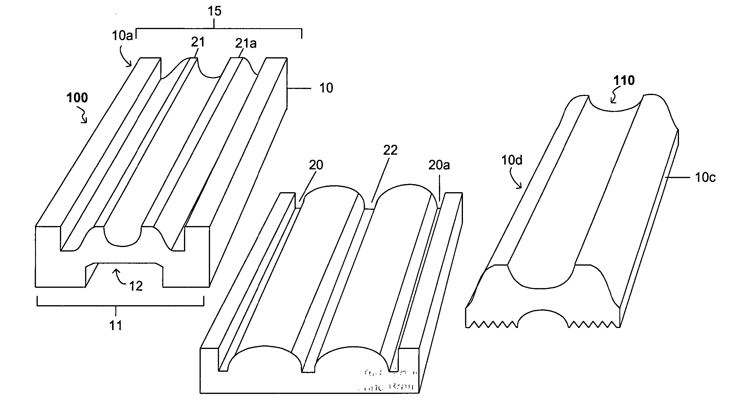
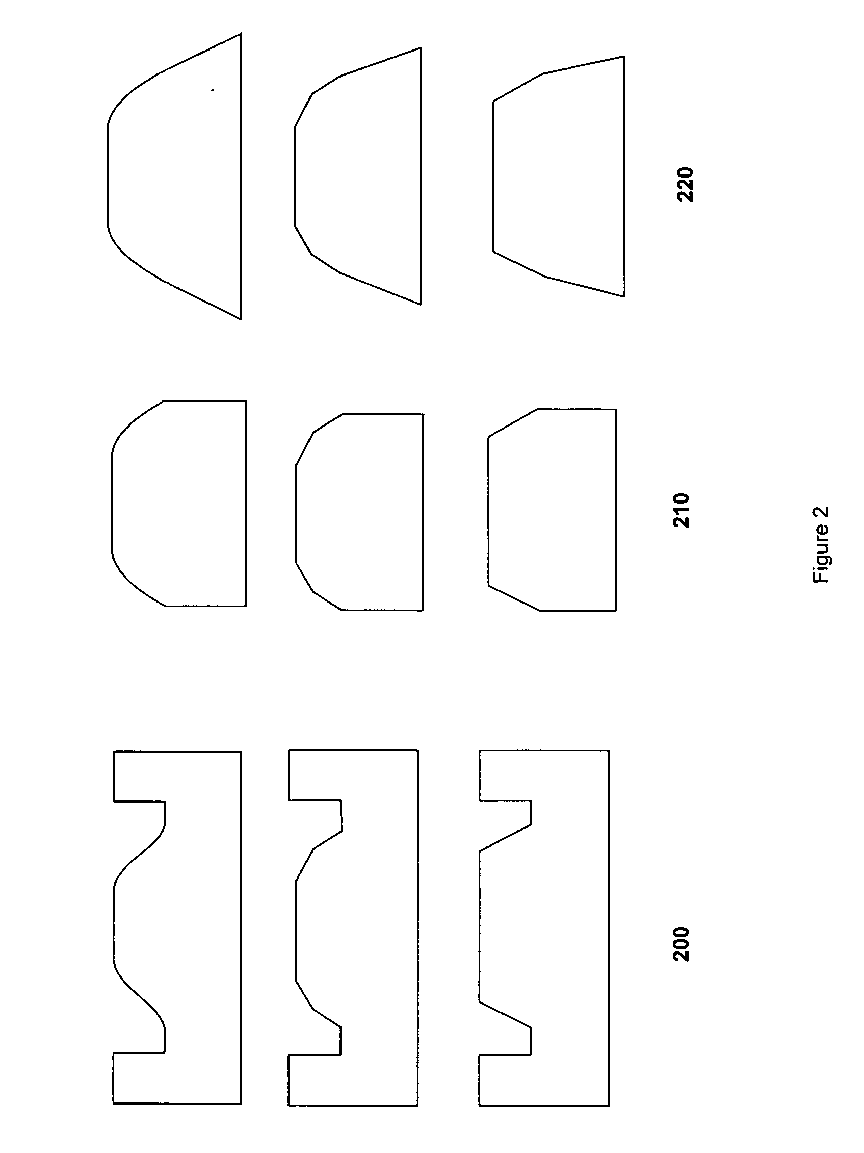
[0034] Referring again to FIG. 1, the tie further comprises a top surface 15. The top surface is alternatively shaped to accept the bottom surface of a variety of steel tie. In one embodiment 100 the top surface 15 is approximately 8 inches in linear width. In another embodiment 110, the top surface is approximately 6 inches in width. One skilled in the art should readily realize that the linear width of the top surface is contemplated to conform to a steel tie to be attached and thus is not restricted to the examples provided. In an embodiment, the width of the top surface 15 is substantially equal to the width of the bottom 11. Alternatively, as shown in several embodiments of dies used to shape a tie depicted in FIG. 2, the bottom is wider that the top surface (Column 220). In such embodiments the sides of the tie form acute angles with the bottom.
[0035] The top surface 15 of the tie is alternatively shaped to receive a variety of steel ties. The invention is adaptable to receive...
embodiment 100
[0039] In an embodiment 100 depicted in FIG. 1 and shaped to support a trough steel tie, the top surface 15 comprises a modified convex curve extending from the indent 20, 20a to a first high point 21 and a second high point 21a. Such curves support the bottom surface of the steel tie. Alternatively, the curves may comprise channels or grooves to reduce the weight of the tie in areas not essential to support the steel tie and the railway.
[0040] As shown in several embodiments of dies used to shape the top surface 15 depicted in FIG. 4, the top surface may alternately be planar, rounded, and or angled. The top surface may or may not be essentially parallel to the bottom.
[0041] In an embodiment, the tie is channeled in an area corresponding to a center piece of a trough or grooved steel tie. The channel 22 runs the length of the tie and is adapted to receive at least one bolt to secure the steel tie to the tie of the invention. The tie may be optionally drilled at one or more predete...
PUM
 Abstract
Description
Claims
Application Information