Compact RF antenna

a technology of rf antennas and antenna supports, applied in the direction of antennas, antenna supports/mountings, radiating element structural forms, etc., to achieve the effect of small volum

Inactive Publication Date: 2005-10-27
AMPHENOL SOCAPEX
View PDF6 Cites 29 Cited by
  • Summary
  • Abstract
  • Description
  • Claims
  • Application Information

AI Technical Summary

Benefits of technology

[0010] An object of the present invention is to provide a compact antenna suitable for use in a porta...

Problems solved by technology

Nevertheless, most such antennas are not only of dimensions that are too great, but their ground planes are ...

Method used


Image

  • Compact RF antenna
  • Compact RF antenna
  • Compact RF antenna

Examples


Embodiment Construction

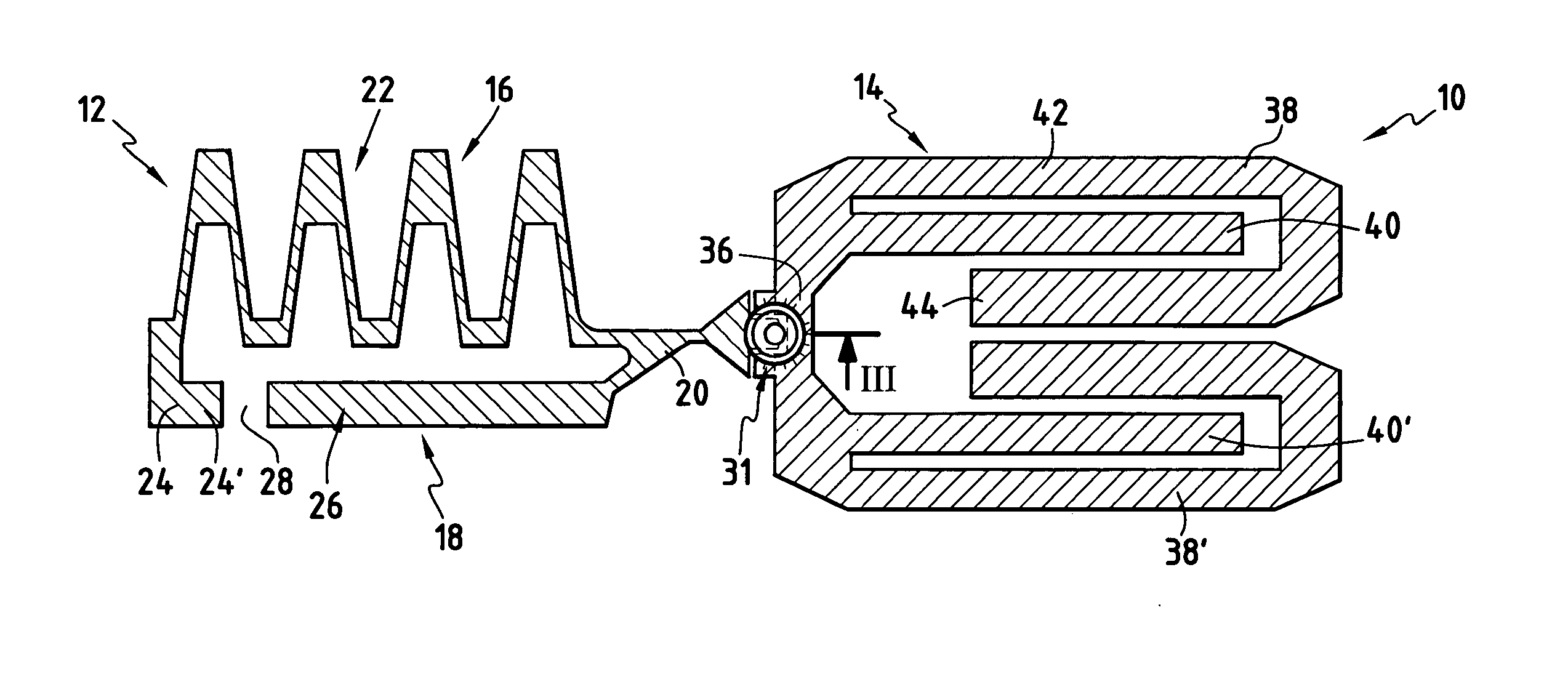
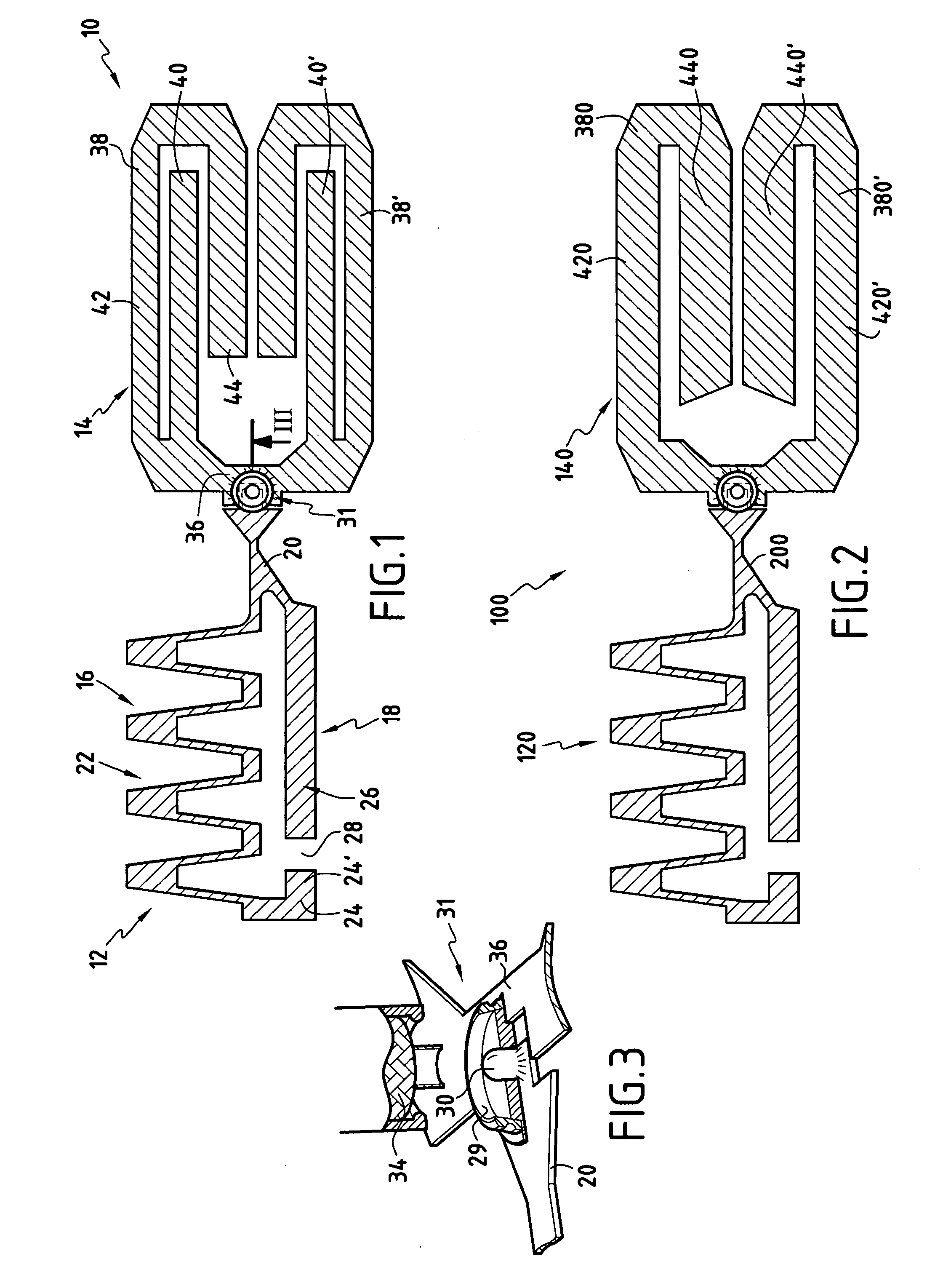
[0052] With reference to FIG. 1, there follows a description of a compact antenna 10 constituting a first embodiment.

[0053] The compact antenna 10 is preferably designed to operate at mobile telephony frequencies: GSM 850 / 900 MHz, DCS 1800 MHz; PCS 1900 MHz, and UMTS 2100 MHz.

[0054] To explain the operation of the antenna, a lowest cellular frequency is defined as is a highest cellular frequency.

[0055] The lowest cellular frequency is about 850 MHz and the highest cellular frequency is about 2100 MHz.

[0056] These two cell phone frequencies do not constitute the frequency operating limits of the compact antenna, but serve to describe the architecture and to explain the operation of the compact antenna. It is possible to use the compact antenna at a frequency higher than the highest cellular frequency, in particular at UMTS frequencies of the order of 2100 MHz.

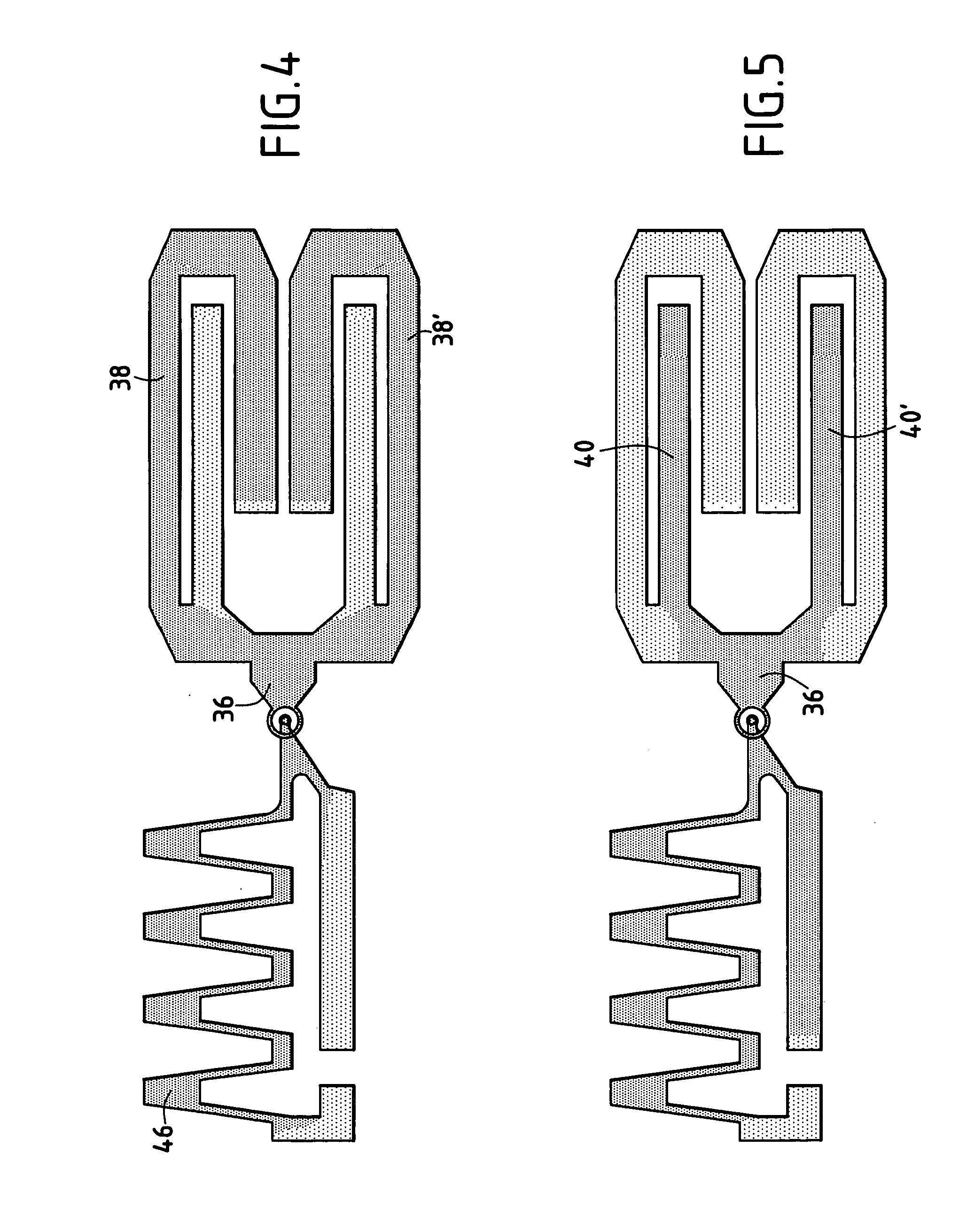
[0057] The compact antenna 10 as shown comprises an electrical circuit printed on insulation (not shown). This insulation...


PUM


Abstract

A monopole type antenna suitable for operating in cellular frequency bands, the antenna comprising: a conductive surface forming a radiating element and including an electrical connection zone; a compact conductive counterpoise including a connection zone; and a feed line comprising an antenna cable connected to the connection zones of said radiating element and of said compact counterpoise. In the antenna, said radiating element is in the form of an open loop having two branches both connected to the antenna cable and defining first and second radiating portions, each of the radiating portions is suitable for entering into resonance at at least one cellular frequency and extends in a main direction; and these two main directions are substantially parallel so as to operate parasitically and with coupling between the two radiating portions.

Description

FIELD OF THE INVENTION [0001] The present invention relates to a compact antenna of the monopole type for transmitting and receiving signals, and suitable for use particularly, but not exclusively, in a portable terminal operating on different frequency bands. [0002] More precisely, the invention relates to a compact antenna of the monopole type comprising: [0003] a conductive surface forming a radiating element and including an electrical connection zone; [0004] a compact conductive counterpoise including a connection zone; and [0005] a feed line comprising an antenna cable connected to the connection zones of said radiating element and of said compact counterpoise. BACKGROUND OF THE INVENTION [0006] At present, the specifications of an antenna must satisfy at least two requirements: firstly the antenna must be capable of operating at the different frequency bands of the available types of network; and secondly the dimensions of the antenna must be adapted to the ever-smaller dimen...

Claims


Application Information

Patent Timeline
IPC IPC(8): H01Q1/24H01Q1/36H01Q1/48H01Q5/10H01Q9/38H01Q9/42
CPCH01Q1/243H01Q1/48H01Q1/36
Inventor ANNABI, AYOUBLECLERC, DANIELDIXIMUS, FREDERIC
Owner AMPHENOL SOCAPEX
Why Eureka
Try Eureka