Grid canvas

a grid canvas and object technology, applied in the field of computer graphics, can solve the problems of poor case presentation, inability to get all the elements to resize in an intelligent manner, and inability to meet the needs of users,

Inactive Publication Date: 2005-10-27
MICROSOFT TECH LICENSING LLC
View PDF5 Cites 76 Cited by
  • Summary
  • Abstract
  • Description
  • Claims
  • Application Information

AI Technical Summary

Benefits of technology

[0011] The present invention is directed to a layout that resizes intelligently without complexity. Elements (i.e., objects) are attached to a virtual grid of row and column gridlines, which are defined separately. The relationship between objects and the grid is bi-directional so that moving one (gridline or object) will affect the othe

Problems solved by technology
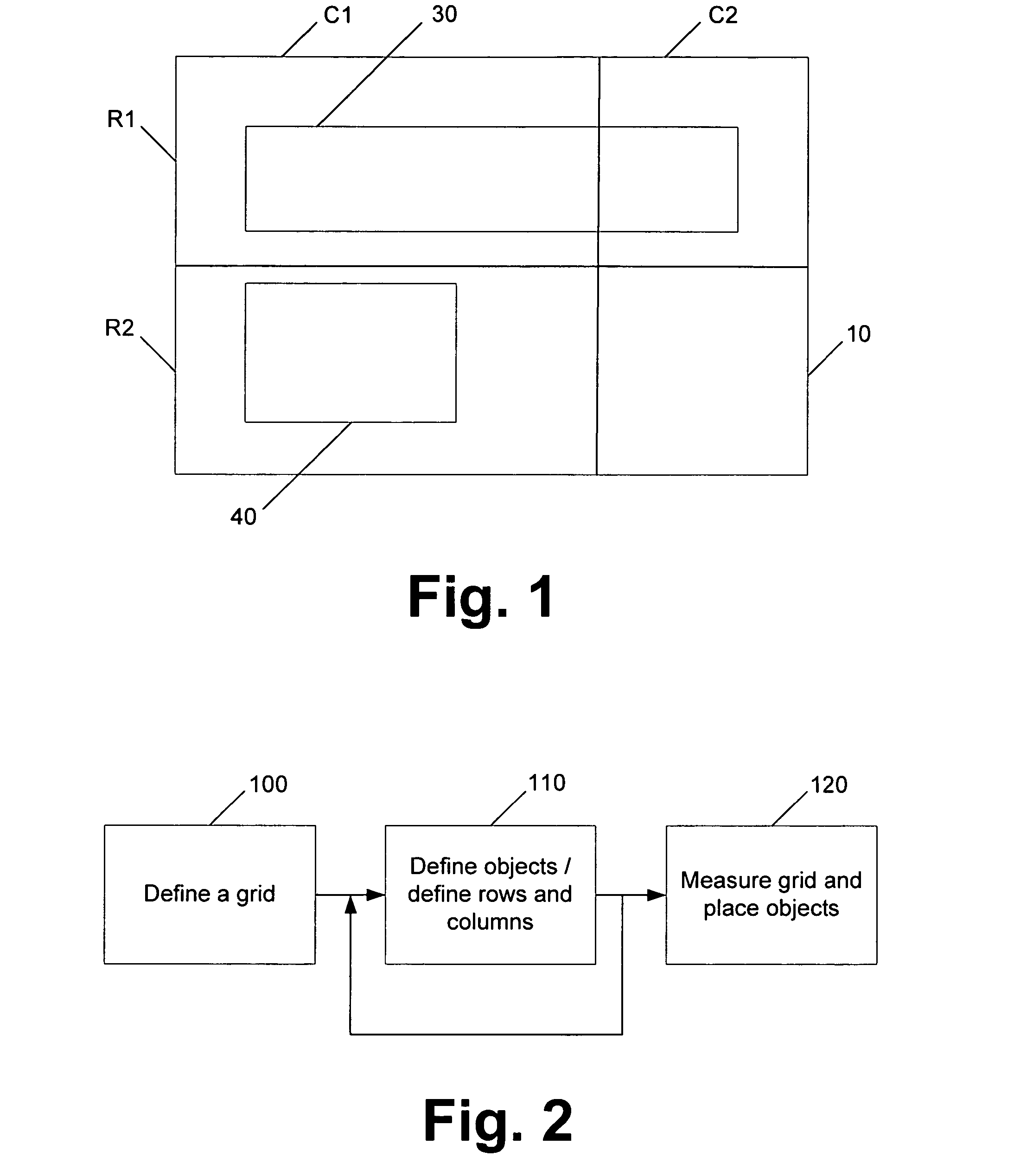
However, as the application is built and the area covered by the canvas is resized, it becomes difficult to get all the elements to resize in an intelligent manner.
Current approaches tend to be incomplete, complex, or opaque to the designer.
Creating an application layout that resizes intelligently is a problem that is currently approached by incomplete mechanisms, exceedingly complex mechanisms, or code that is inaccessible to a designer.
This type of layout is acceptable for a fixed-function user interface that is intended to grow larger with i

Method used


Image

  • Grid canvas
  • Grid canvas
  • Grid canvas

Examples


Embodiment Construction

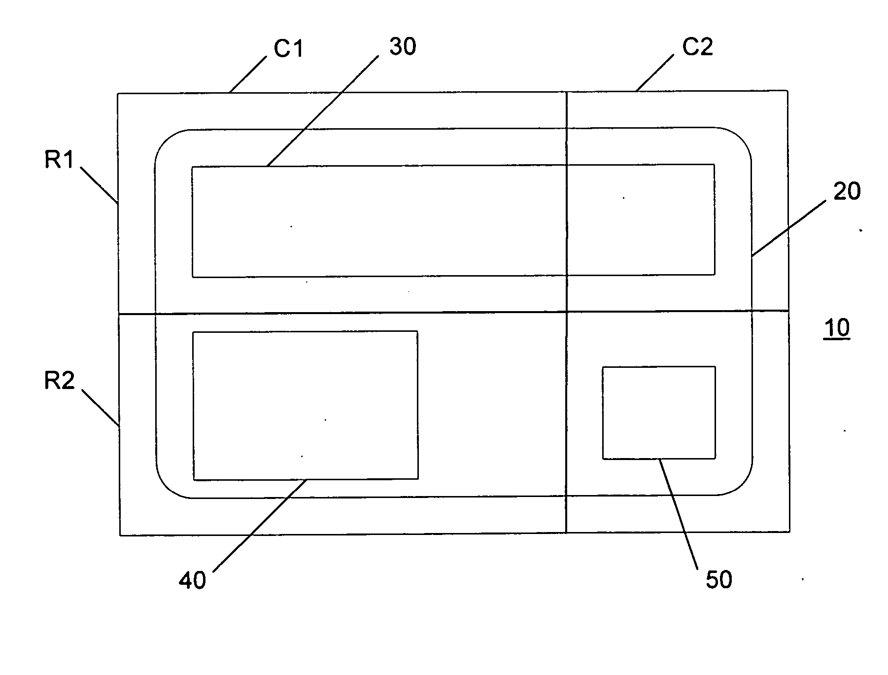
[0024] The present invention is directed to a layout in which objects are attached to a virtual grid of row and column gridlines, which are defined separately. The relationship between objects and grid is bi-directional so that expanding / collapsing the object will push the gridlines, and moving the gridline will expand / collapse the object. Such a layout mechanism is referred to herein as the “grid canvas” layout mechanism.

[0025] An exemplary grid canvas layout is shown in FIG. 1. The grid canvas layout mechanism is a cooperation between the parent and the children. The parent 10 is effectively a canvas on which objects 30, 40 can be drawn on at will in any location, and objects remain where placed. At any time, the grid canvas 10 may be split into as many rows R and columns C as desired. Each child of the grid canvas maintains a grid bounding box, along with margins relative to that box. For example, the grid bounding box for object 30 is all of row R1 (i.e., R1C1:R1C2). Margin set...


PUM


Abstract

A layout resizes intelligently without complexity. Objects or elements are attached to a virtual grid of row and column gridlines, which are defined separately. The relationship between the objects and the grid is bi-directional so that moving one (gridline or object) will affect the other (object or gridline). In other words, expanding/collapsing the object will push the gridlines, and moving the gridline will expand/collapse the object. The virtual grid can be created before or after the objects to provide further flexibility. A child object can have its own virtual grid, which allows fine-grained control where desired.

Description

FIELD OF THE INVENTION [0001] This invention relates in general to the field of computer graphics. More particularly, this invention relates to the layout of objects on a display. BACKGROUND OF THE INVENTION [0002] When designing the layout of user interface elements (window regions, controls, etc.), a designer canvas is often used and elements (also referred to herein as objects) are dropped onto the canvas. However, as the application is built and the area covered by the canvas is resized, it becomes difficult to get all the elements to resize in an intelligent manner. Current approaches tend to be incomplete, complex, or opaque to the designer. [0003] It is desirable to design a layout so that it resizes without the designer having to write code to make it happen. Creating an application layout that resizes intelligently is a problem that is currently approached by incomplete mechanisms, exceedingly complex mechanisms, or code that is inaccessible to a designer. [0004] A conventi...

Claims


Application Information

Patent Timeline
IPC IPC(8): G06T11/80G06T11/60
CPCG06T11/60G06F9/4443G06F9/451G06T3/40
Inventor YOUNG, KENNETH LAWRENCEOVETCHKINE, OLEG V.TITOV, DMITRY G.FARADAY, PETERCOOPER, KENNETH
Owner MICROSOFT TECH LICENSING LLC
Why Eureka
Try Eureka