Optical beam detection device and optical beam detection system using therewith

a detection device and optical beam technology, applied in the direction of direction/deviation determining electromagnetic systems, optical radiation measurement, instruments, etc., can solve the problems of extremely weak light receiving elements, device inconvenience, and problematic fall in signal-to-noise ratio (s/n) ratio, so as to reduce the deviation of the optical axis

Inactive Publication Date: 2005-10-27
OLYMPUS CORP +1
View PDF16 Cites 9 Cited by
  • Summary
  • Abstract
  • Description
  • Claims
  • Application Information

AI Technical Summary

Benefits of technology

[0025] It is desirable that the optical system according to the present invention further comprise an adjusting member for adjusting the inclination of the whole of the optical system with respect to light beams that are approaching

Problems solved by technology

However, this device has an inconvenience in that, when employed in spatial light communications that have an optical tracking function, a portion of the received light is always used for detecting the inclination of the optical axis.
In the case of long-distance communications in particula

Method used


Image

  • Optical beam detection device and optical beam detection system using therewith
  • Optical beam detection device and optical beam detection system using therewith
  • Optical beam detection device and optical beam detection system using therewith

Examples


first embodiment

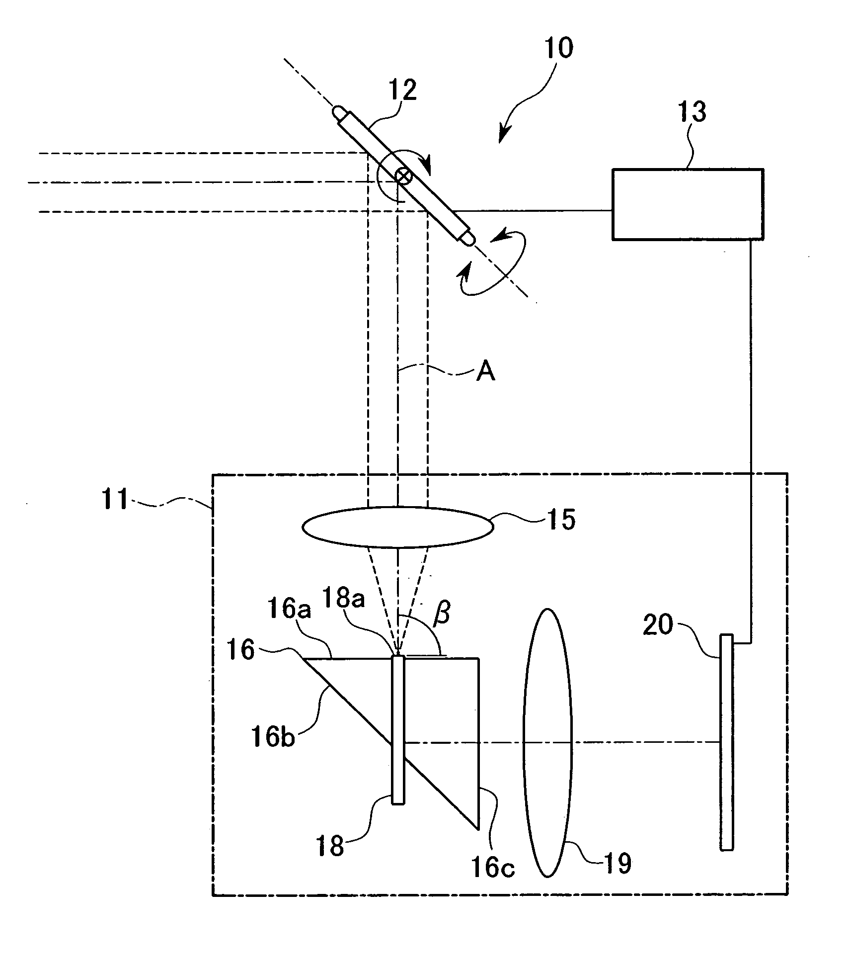
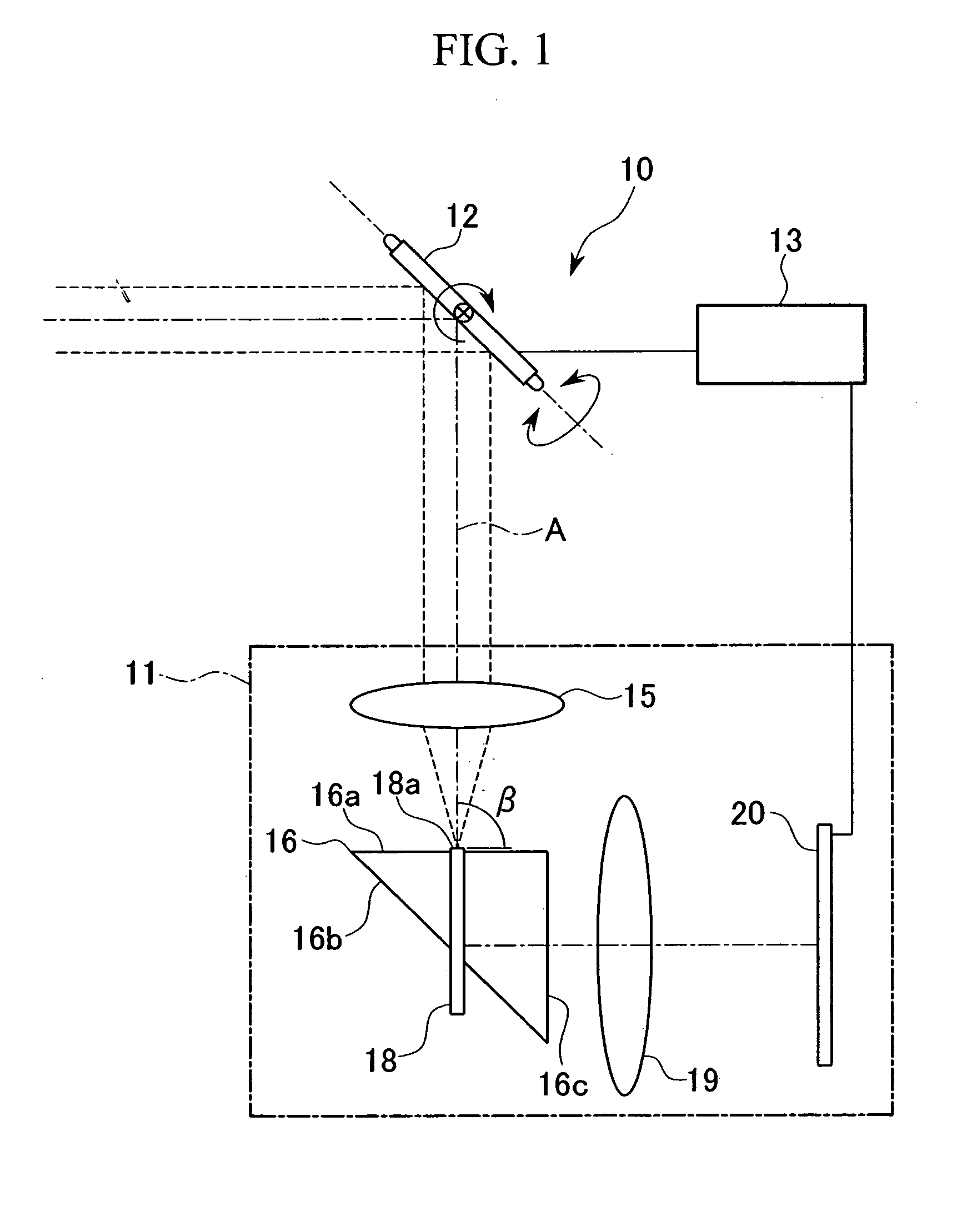
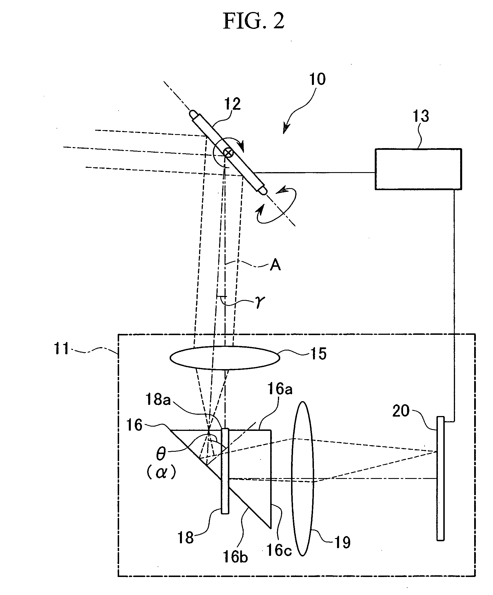
[0038]FIGS. 1 and 2 show an optical system 10 according to the present invention. This optical system 10 is a system for receiving light transmitted from the outside, and is equipped with an optical beam detection device 11 for detecting the deviation in the optical axis of signal light beams transmitted from the outside; a light deflecting element, such as a galvano mirror 12 for example, for directing signal light beams transmitted from the outside into optical beam detection device 11; and a controller 13 for calculating and outputting the amount of correction required for driving galvano mirror 12 in a direction which reduces the deviation in the optical axis based on the detection signal for the deviation in the optical axis of the light beams that is detected by optical beam detection device 11.

[0039] Galvano mirror 12 is capable of rotation centered on the two axes, X and Y, and can be tilt driven in an optional angular direction.

[0040] Optical beam detection device 11 is pr...

second embodiment

[0063] Note that in the above-described second embodiment, the incident end surface 18a of optical fiber 18 is formed in a direction which is perpendicular to reference optical axis A. However, alternatively, it is also acceptable to incline the end surface of incident end surface 18a so as to be in the same plane as reflecting surface 23a, as shown in FIG. 9. In this way, with regard to the end surface of optical fiber 18, cladding 18c, which surrounds core 18b that forms incident end surface 18a, is in the same plane as reflecting surface 23a and forms a portion of reflecting surface 23a. For this reason, the loss of reflected light directed toward CCD 20 becomes even smaller. Note that it is also acceptable to provide a reflective coating layer 24 onto the reflecting surface 23a that is shown in FIG. 9, this coating layer including the end surface of cladding 18c as well.

[0064] Next, examples of modifications of the optical path deflector and light receiving surface for the optic...


PUM


Abstract

The present invention relates to an optical beam detection device for detecting deviation in the optical axis of light beams from a reference optical axis, the optical beam detection device provided with a converging member for converging the light beams; a light receiving surface that is disposed near the position where light beams that have an optical axis that coincides with the reference optical axis are converged by the converging member; an optical path deflector for deflecting light beams that have an optical axis that deviates from the reference optical axis, after they have passed through the converging member; and a light detecting element for detecting the light beams that have been deflected by the optical path deflector.

Description

BACKGROUND OF THE INVENTION [0001] 1. Field of the Invention [0002] The present invention relates to an optical beam detection device and an optical system using therewith. More specifically, the present invention relates to an optical beam detection device that detects the optical axis inclination in a light receiving device used for optical tracking in spatial light communications. The present invention further relates to an optical system using therewith. [0003] Priority is claimed on Japanese Patent Application No. 2004-56769, filed Mar. 1, 2004, the content of which is incorporated herein by reference. [0004] 2. Description of Related Art [0005] As a conventional optical beam detection device, there is a design in which a portion of the light beams are branched at a beam splitter, and are received at a quadrant ditector or other such optical sensor. The direction of inclination of the optical axis of the light beams is then detected based on the position of the received light s...

Claims


Application Information

Patent Timeline
IPC IPC(8): G01J1/00G01B11/26G01J1/06G01S3/782G01S3/784G02B26/10G02B27/14
CPCG01J1/0266G01J1/0414G01J1/0451G01J1/0455G02B27/143G02B26/101G02B27/108G02B27/126G01S3/784
Inventor TAKAHASHI, KOICHIARIMOTO, YOSHINORI
Owner OLYMPUS CORP
Why Eureka
Try Eureka