Scanning optical apparatus

a scanning optical apparatus and optical box technology, applied in the field of scanning optical apparatus, can solve the problems of insufficient structure to secure vibration-proof performance, limited area for forming rib structure for reinforcement, and inability to physically adjust the optical axis, so as to reduce the deviation of the optical axis and increase the strength of the optical box upper surface portion of the scanning optical apparatus

Inactive Publication Date: 2013-02-05
CANON KK
View PDF11 Cites 0 Cited by
  • Summary
  • Abstract
  • Description
  • Claims
  • Application Information

AI Technical Summary

Benefits of technology

[0012]The present invention is directed to a scanning optical apparatus that can adjust an optical axis emitted from a scanning optical box while strength of an optical box upper surface portion of the scanning optical apparatus is increased. Further, the present invention is directed to a scanning optical apparatus that can reduce deviation of an optical axis emitted from a scanning optical box if a covering member that covers an upper surface of the optical box of the scanning optical apparatus is provided.

Problems solved by technology

Further, optical paths in each optical system need to be ensured in the optical box, so that areas for forming rib structure for reinforcement are limited.
However, the structure is not sufficient to secure a vibration-proof performance against an external vibration and to reduce torsion of a frame of the optical box that causes positional deviation of an optical element.
However, such a covering member has the following problem.
However, adjustment of the optical axis is not physically possible in the state that the covering member is mounted.
However, the high-stiffness covering member mounted over the entire optical box upper surface will cause deformation of the optical box due to fitting of the optical box to the shape of the covering member if the covering member has even a small problem with accuracy.

Method used


Image

  • Scanning optical apparatus
  • Scanning optical apparatus
  • Scanning optical apparatus

Examples


Embodiment Construction

[0019]Various exemplary embodiments, features, and aspects of the invention will be described in detail below with reference to the drawings.

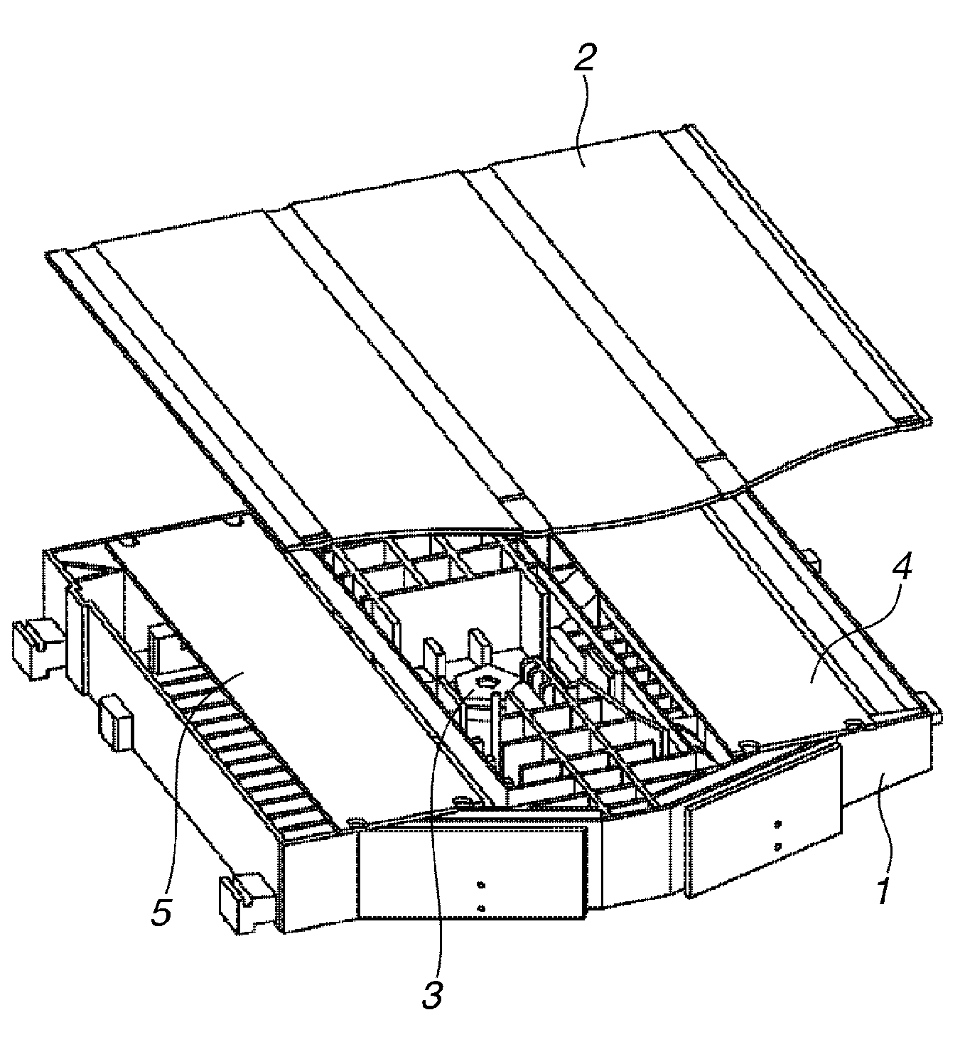
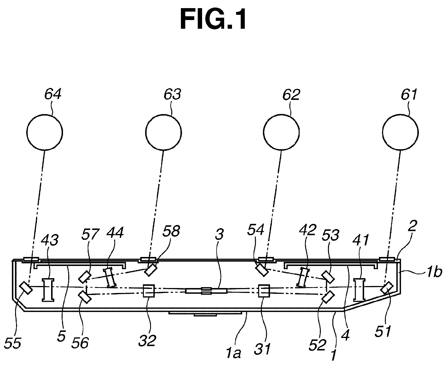
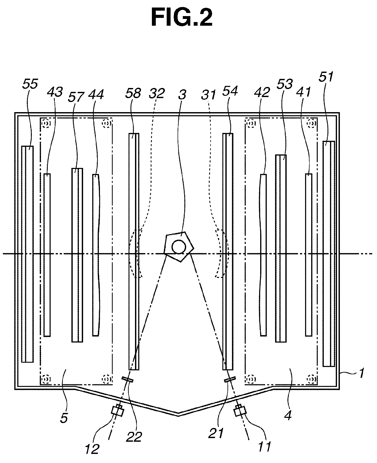
[0020]FIGS. 1 to 3 illustrate example structures of a scanning optical apparatus according to an exemplary embodiment of the present invention. FIG. 1 is a cross sectional view illustrating mainly a portion disposed after a deflector in a scanning optical apparatus mounted on a tandem type color image forming apparatus that uses four photosensitive drums. FIG. 2 is a plan view illustrating positions of the deflector, imaging lenses, and reflecting mirrors from light sources in the scanning optical apparatus in a state that a cover is removed. FIG. 3 is an exploded perspective view illustrating a structure of the scanning optical apparatus.

[0021]The scanning optical apparatus includes an optical box 1, a cover 2, and reinforcing members 4 and 5 as a housing. The optical box 1 includes a bottom plate 1a as a bottom part (bottom plate portion), an...


PUM


Abstract

A scanning optical apparatus includes a deflection element configured to deflect a laser beam emitted from a light source for scanning, a mirror member configured to directly reflect the laser beam deflected by the deflection element toward a surface to be scanned, and an optical box configured to house the deflection element and the mirror member. The optical box includes a bottom plate portion and a sidewall portion that encloses the bottom plate portion. The scanning optical apparatus further includes a plate-shaped connection portion configured to connect an opening surface of the optical box that faces the bottom plate portion from one side to the other side of the sidewall portion. The connection portion is provided at a position where it does not overlap with the mirror member in a direction orthogonal to the bottom plate portion.

Description

BACKGROUND OF THE INVENTION[0001]1. Field of the Invention[0002]The present invention relates to a scanning optical apparatus that is used in image forming apparatuses such as an electrophotographic copying machine and a laser printer.[0003]2. Description of the Related Art[0004]In a scanning optical apparatus that is used in an image forming apparatus such as an electrophotographic copying machine and a laser printer, generally, an optical beam emitted from a light source is deflected by a deflector and is condensed by an imaging optical system such as an f-theta lens to form a beam spot on a photosensitive drum. The scanning optical apparatus scans the photosensitive drum surface with the beam spot.[0005]A laser beam deflected and scanned within an optical box forms an image using an optical lens, and the image is reflected by reflecting mirrors toward the photo sensitive drum. In the process, if a relative position of the optical lens is deviated by a vibration or deformation of ...

Claims


Application Information

Patent Timeline
Patent Type & Authority Patents(United States)
IPC IPC(8): G02B26/08
CPCB41J2/473G02B26/123
Inventor UDUKI, KAZUO
Owner CANON KK
Why Eureka
Try Eureka