Radio base station device, communication terminal device, and control information transmission method

a technology of communication terminal and radio base station, which is applied in the direction of power management, multiplex communication, and assessment restriction, etc., can solve the problems of overconsumption of downlink spreading code resources, error correction of transmission data, and increase of overhead, so as to suppress consumption of spreading code resources

Active Publication Date: 2005-10-27
PANASONIC INTELLECTUAL PROPERTY CORP OF AMERICA
View PDF19 Cites 117 Cited by
  • Summary
  • Abstract
  • Description
  • Claims
  • Application Information

AI Technical Summary

Benefits of technology

[0045] Thus, the radio base station apparatus spreads control information directed to a plurality of terminals using a spreading code common to the respective communication terminal apparatuses, and can thereby suppress consumption of spreading code resources on a downlink, and the communication terminal apparatuses can extract control information directed to the own station adequately from the multiplexed signal according to the preset multiplexing rule.

Problems solved by technology

Before being multiplexed, the transmission data is subjected to error correcting coding.
As a result, there is a problem that resources of downlink spreading codes are overconsumed.
This causes a problem that overhead increases and transmit power resources on a downlink are overconsumed.
Furthermore, when downlink transmit power resources are overconsumed, interference with other cells increases, leading to a reduction of a system capacity.
On the other hand, as indicated in “3GPP, R1-030177, Downlink physical channel structure”, that is, as is implemented with the configurations shown in FIG. 1 and FIG. 2, when the downlink control information for forming an uplink packet signal is embedded in a dedicated channel of each communication terminal which is carrying out uplink packet transmission, it is possible to transmit control information to all communication terminals, but there is also a problem of producing adverse effects on existing dedicated channels.
Moreover, transmitting downlink control information embedded in the existing dedicated channels without errors needs to increase transmit power of the downlink control information, which results in a problem that the downlink transmit power resources are overconsumed.
For example, when control information is embedded in a data channel called “DPDCH” (channel to mainly transmit speech data and signaling, etc., from a higher level apparatus), the number of bits on a physical channel available for dedicated channel data is decreased, which leads to a problem that the quality of transmission data deteriorates.
But this also deteriorates the reception performance of TFCI, increasing the probability that reception processing of dedicated channels will not be performed correctly.
Furthermore, when a standardization specification using dedicated channels is already determined, changing the standardization specification of a downlink dedicated channel produces another problem that not only a test on uplink channel packet transmission but also a test on dedicated channels needs to be done again.

Method used


Image

  • Radio base station device, communication terminal device, and control information transmission method
  • Radio base station device, communication terminal device, and control information transmission method
  • Radio base station device, communication terminal device, and control information transmission method

Examples


embodiment 1

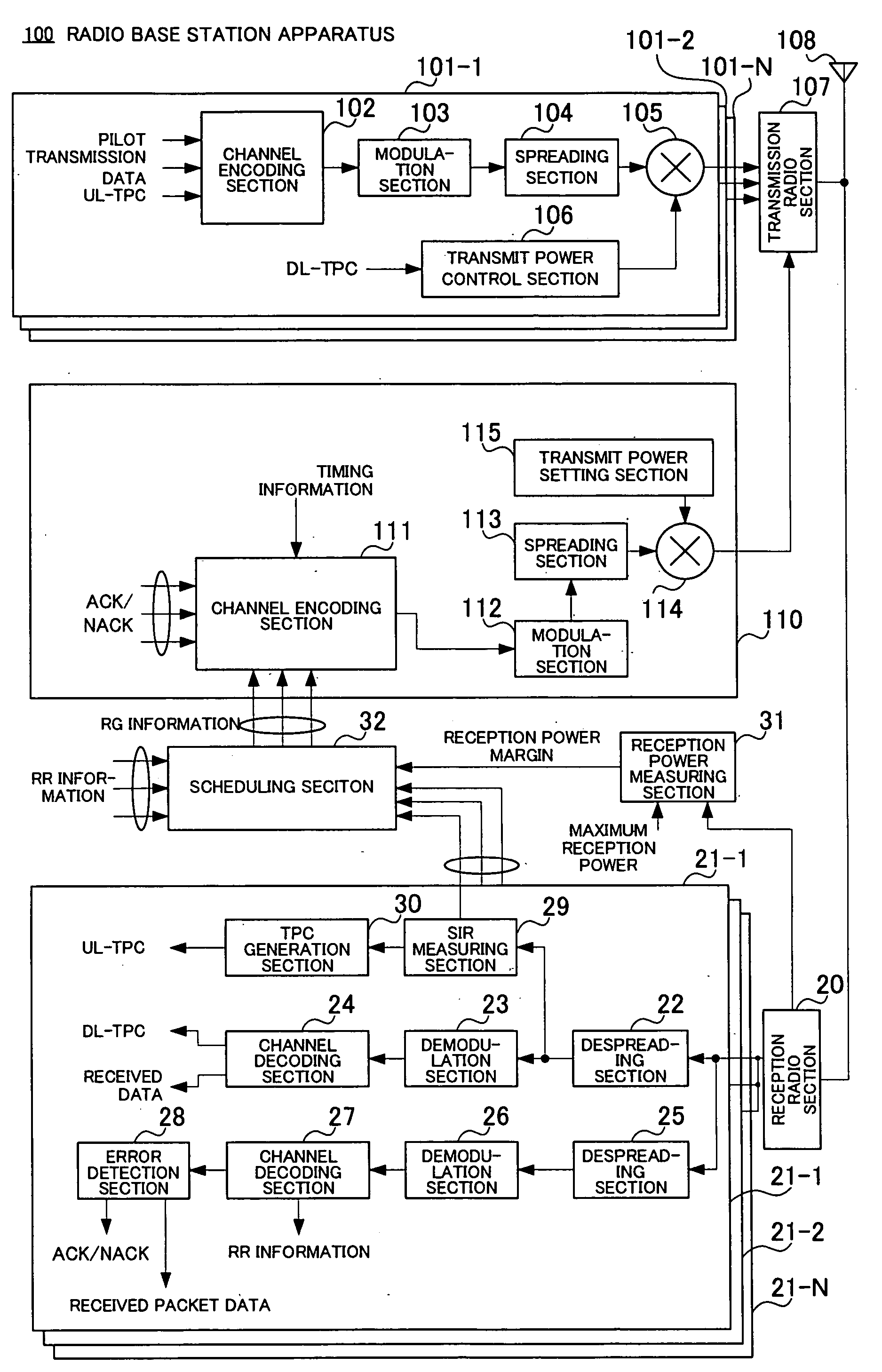
[0074]FIG. 4 illustrates the configuration of a radio base station apparatus according to Embodiment 1 of the present invention. The radio base station apparatus 100 is provided with dedicated channel signal formation units 101-1 to 101-N corresponding in number to communication terminals carrying out communication and a control information channel signal formation unit 110.

[0075] The dedicated channel signal formation units 101-1 to 101-N function as a first transmission signal formation section, spread transmission data directed to each communication terminal using a spreading code assigned to each communication terminal and thereby form a dedicated channel signal directed to each communication terminal.

[0076] On the other hand, the control information channel signal formation unit 110 functions as a second transmission signal formation section, multiplexes control information directed to each communication terminal for each communication terminal to carry out uplink packet tran...

embodiment 2

[0111] This embodiment proposes that spreading codes are changed according to the type of control information taking into consideration the fact that transmitting control information directed to a plurality of communication terminals by diverting the PICH data structure as in the case of Embodiment 1 produces limits to the number of transmittable control information pieces and the number of communication terminals.

[0112] For example, as shown in FIG. 9, in a system with the number of paging indicators Np in one frame set to Np=144, there are 144 combinations of communication terminals and control information pieces that can be transmitted in one frame, while in a system with Np=18, the repetition count of bits in a paging indicator increases, and therefore only 18 combinations between communication terminals and control information pieces that can be transmitted in one frame can be secured. Focused on the fact that the number of transmittable control information pieces or the numbe...

embodiment 3

[0128] This embodiment proposes a method of transmitting to communication terminals control information on uplink packet transmission multiplexed using signatures. More specifically, this is a method of providing a plurality of symbol patterns which is multiplexed but still separable (that is, mutually uncorrelated or quasi-uncorrelated), assigning one or a plurality of symbol patterns to one communication terminal and changing polarities of the symbol patterns according to the contents of control information to be transmitted.

[0129]FIG. 15 in which the components corresponding to those in FIG. 4 are assigned the same reference numerals shows the configuration of a radio base station apparatus according to Embodiment 3 of the present invention. The radio base station apparatus 300 has a configuration similar to that of the radio base station apparatus 100 in Embodiment 1 except that signature information is input to a channel encoding section 302 and control information of an uplin...


PUM


Abstract

In addition to dedicated channel signal formation units 101-1 to 101-N, control information channel signal formation unit 110 is provided and this control information channel signal formation unit 110 forms control information for carrying out uplink packet transmission. The control information channel signal formation unit 110 multiplexes control information (RG information, ACK/NACK, etc.) directed to a plurality of communication terminals through a channel encoding section 111 according to a multiplexing rule preset between the base station apparatus and each communication terminal and spreads the control information using a spreading code common to the communication terminals through a spreading section 113 and thereby forms a control information channel signal for uplink packet transmission.

Description

TECHNICAL FIELD [0001] The present invention relates to a technology for transmitting control information necessary for a communication terminal to form an uplink transmission packet from a radio base station to the communication terminal. BACKGROUND ART [0002] Conventionally, various improvements have been made about a scheme for enabling high-speed packet transmission on a downlink from a radio base station to a communication terminal (e.g., HSDPA (High Speed Downlink Packet Access)). This entails an expansion which enables large-volume or low delay data transmission on an uplink channel from the communication terminal to the radio base station, too, and studies on a scheme for realizing high-speed packet communication on an uplink channel (e.g., Enhanced Uplink DCH) are underway. [0003] As with the downlink, studies on the introduction of a scheduling technology for an expansion of such high-speed packet communication to an uplink channel are also underway. The base station carri...

Claims


Application Information

Patent Timeline
Patent Type & Authority Applications(United States)
IPC IPC(8): H04B7/26H04J13/00H04J13/16H04W28/06H04W48/12H04W52/04H04W72/04H04W76/02
CPCH04W48/12H04J13/16H04W88/08
Inventor IOCHI, HITOSHISUZUKI, HIDETOSHI
Owner PANASONIC INTELLECTUAL PROPERTY CORP OF AMERICA
Why Eureka
Try Eureka