Field installable optical fiber connector having plastic splice holder and metal ferrule holder

a technology splice holders, applied in the field of optical fiber connectors, can solve problems such as stress cracking, increased cost, and increased stress concentration

Inactive Publication Date: 2005-10-27
CORNING CABLE SYST LLC
View PDF21 Cites 110 Cited by
  • Summary
  • Abstract
  • Description
  • Claims
  • Application Information

AI Technical Summary

Problems solved by technology

Accordingly, a metal ferrule holder is typically used when the design of the connector includes a thin wall in the area of the ferrule that results in stress cracking due to stress concentrations when the connector is subjected to a side load.
A small form factor connector includes an even thinner wall in the area of the ferr

Method used


Image

  • Field installable optical fiber connector having plastic splice holder and metal ferrule holder
  • Field installable optical fiber connector having plastic splice holder and metal ferrule holder
  • Field installable optical fiber connector having plastic splice holder and metal ferrule holder

Examples


Embodiment Construction

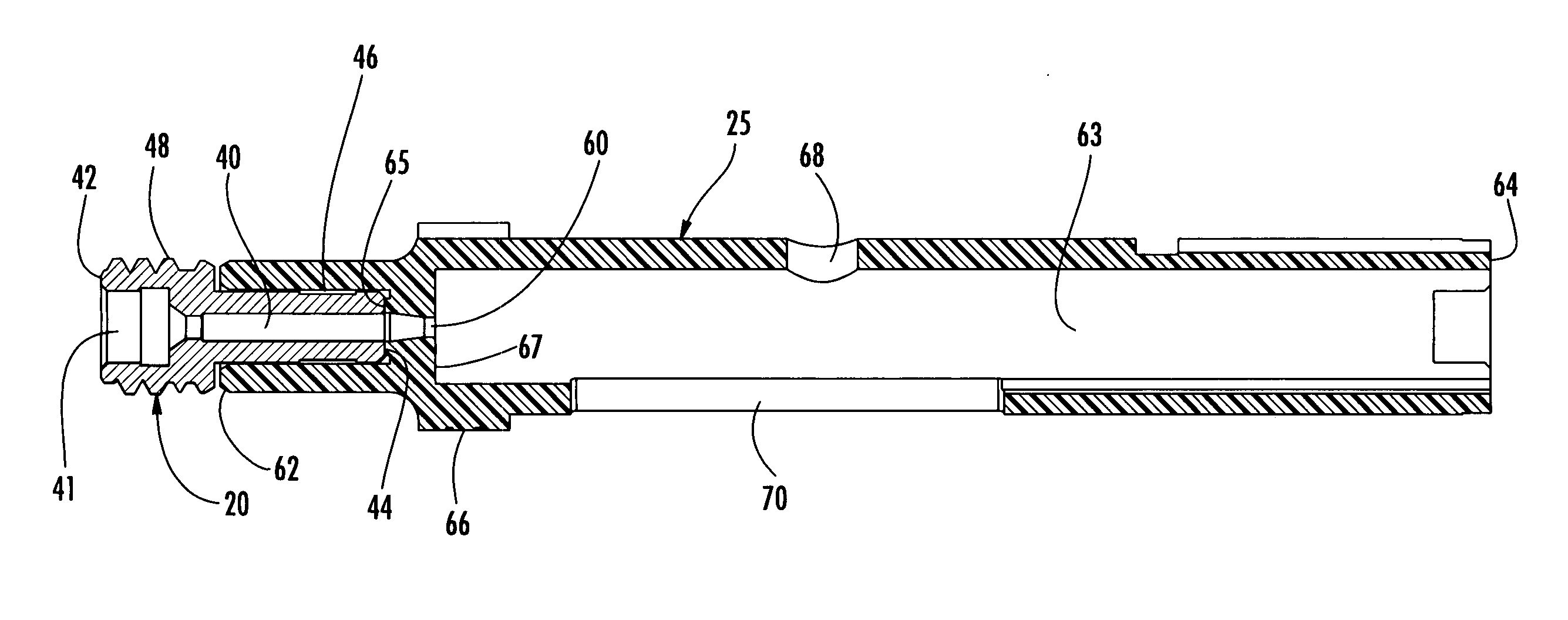
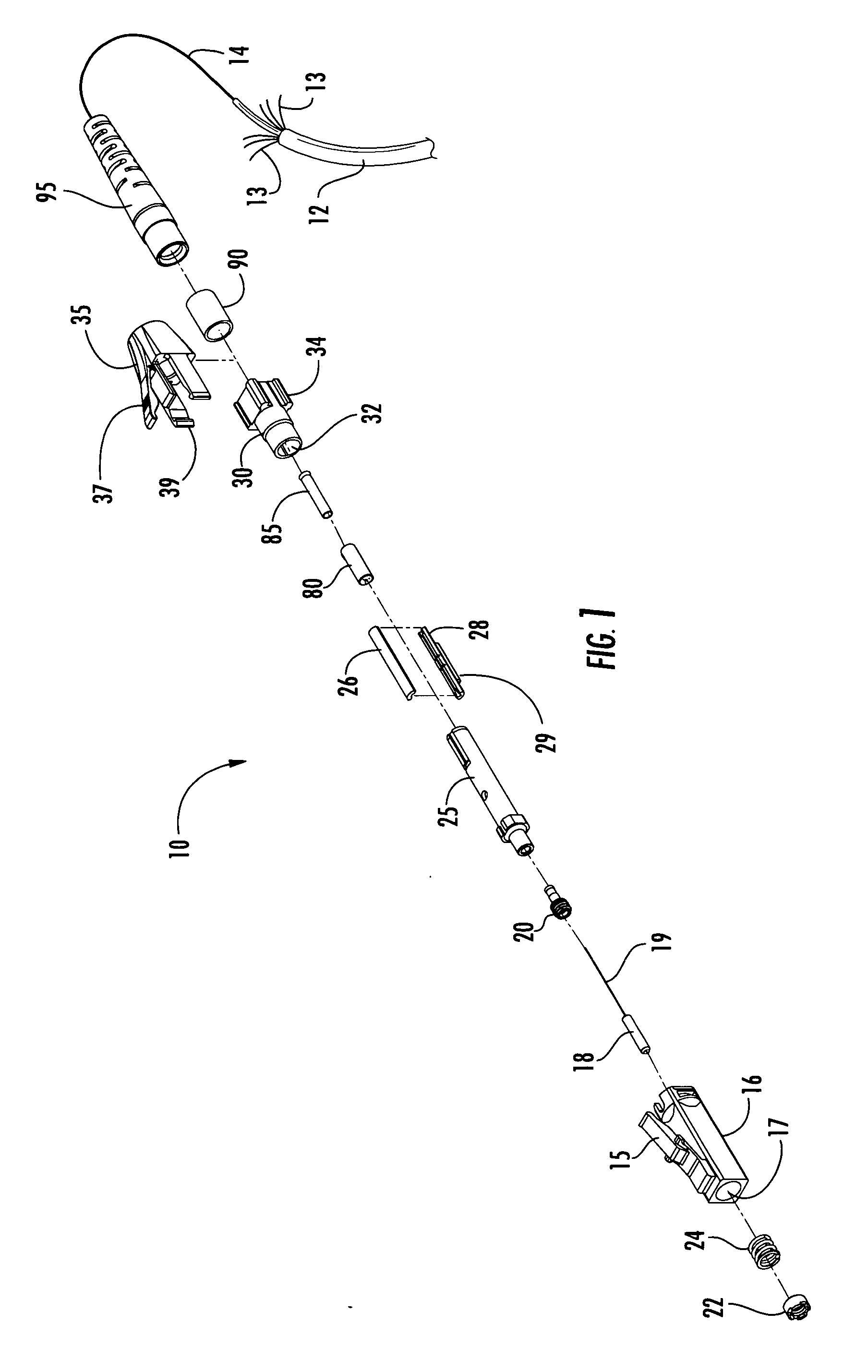
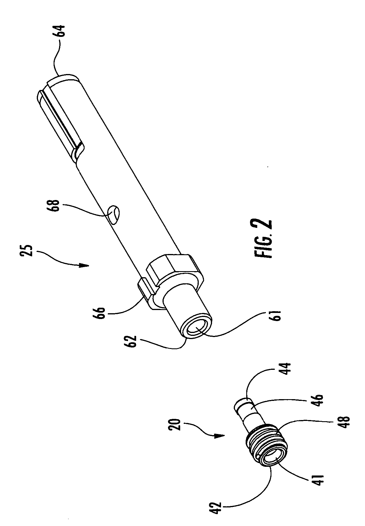
[0013] Reference will now be made to the drawings in which exemplary embodiments of the invention are shown. The drawings together with the following detailed description provide a full and detailed written description of the invention, along with the manner and the process of making and using it, so as to enable one skilled in the pertinent art to make and use it without undue experimentation. The drawings and description also disclose the best mode of carrying out and practicing the invention presently known to the inventors. However, the examples set forth in the drawings and detailed description are provided by way of explanation of the invention and are not intended to limit the scope of the invention in any manner. Thus, this invention is intended to include any modifications and variations of the exemplary embodiments that come within the scope of the appended claims and their equivalents. The detailed description uses numerical and letter designations to refer to features sh...


PUM


Abstract

A field installable optical fiber connector includes a connector housing, a ferrule, a ferrule holder, a splice holder, splice components and a cam member. The splice holder is disposed within the connector housing and defines a first cavity adjacent the forward end and a second cavity adjacent the rearward end. The ferrule holder is fixedly disposed within the first cavity and defines a recess adjacent the forward end. The ferrule is fixedly disposed within the recess and defines a longitudinal bore for receiving an optical fiber stub. The splice components are disposed within the second cavity and configured to receive and secure the optical fiber stub to a field fiber when the cam member disposed about the splice holder is actuated. The splice holder is made of a plastic material and the ferrule holder is made of a metal material to simultaneously satisfy cost, capacity, geometry, strength and machining requirements.

Description

CROSS REFERENCE To RELATED APPLICATIONS [0001] This application is a continuation-in-part of U.S. patent application Ser. No. 10 / 985,541, filed on Nov. 11, 2004, which is a continuation-in-part of U.S. patent application Ser. No. 10 / 808,057, filed on Mar. 24, 2004.BACKGROUND OF THE INVENTION [0002] 1. Field of the Invention [0003] The present invention relates generally to optical fiber connectors, and more particularly, to optical fiber connectors including a connector body made of a plastic material and a ferrule holder made of a metal material. In an exemplary embodiment, the invention is an optical fiber connector configured for performing a mechanical splice including a splice holder made of a plastic material and a ferrule holder made of a metal material. [0004] 2. Technical Background [0005] Optical fiber connectors generally include a ferrule and a ferrule holder that retains the ferrule in a fixed position relative to the ferrule holder. The ferrule holder and the ferrule a...

Claims


Application Information

Patent Timeline
IPC IPC(8): G02B6/36G02B6/38
CPCG02B6/3806G02B6/3893G02B6/3846G02B6/3821
Inventor BARNES, BRANDON A.RAKER, JOSHUA D.
Owner CORNING CABLE SYST LLC
Why Eureka
Try Eureka