Reserve battery

a reserve battery and battery technology, applied in the field of reserve batteries, can solve the problems of increasing the voltage of the cell, raising sanitary and safety concerns, and the shelf life is essentially infinite, and achieve the effect of no deterioration and minimal delay

Inactive Publication Date: 2005-10-27
MORRIS WILLIAM F +7
View PDF5 Cites 23 Cited by
  • Summary
  • Abstract
  • Description
  • Claims
  • Application Information

AI Technical Summary

Benefits of technology

[0006] Therefore, the present invention provides a deferred action dry cell which undergoes substantially no det

Problems solved by technology

Since there is no consumption or reaction with the electrodes under these circumstances, the shelf life is essentially infinite.
One problem encountered in many of the known reserve batteries relates to the ramp up voltage of th

Method used


Image

  • Reserve battery
  • Reserve battery
  • Reserve battery

Examples


Embodiment Construction

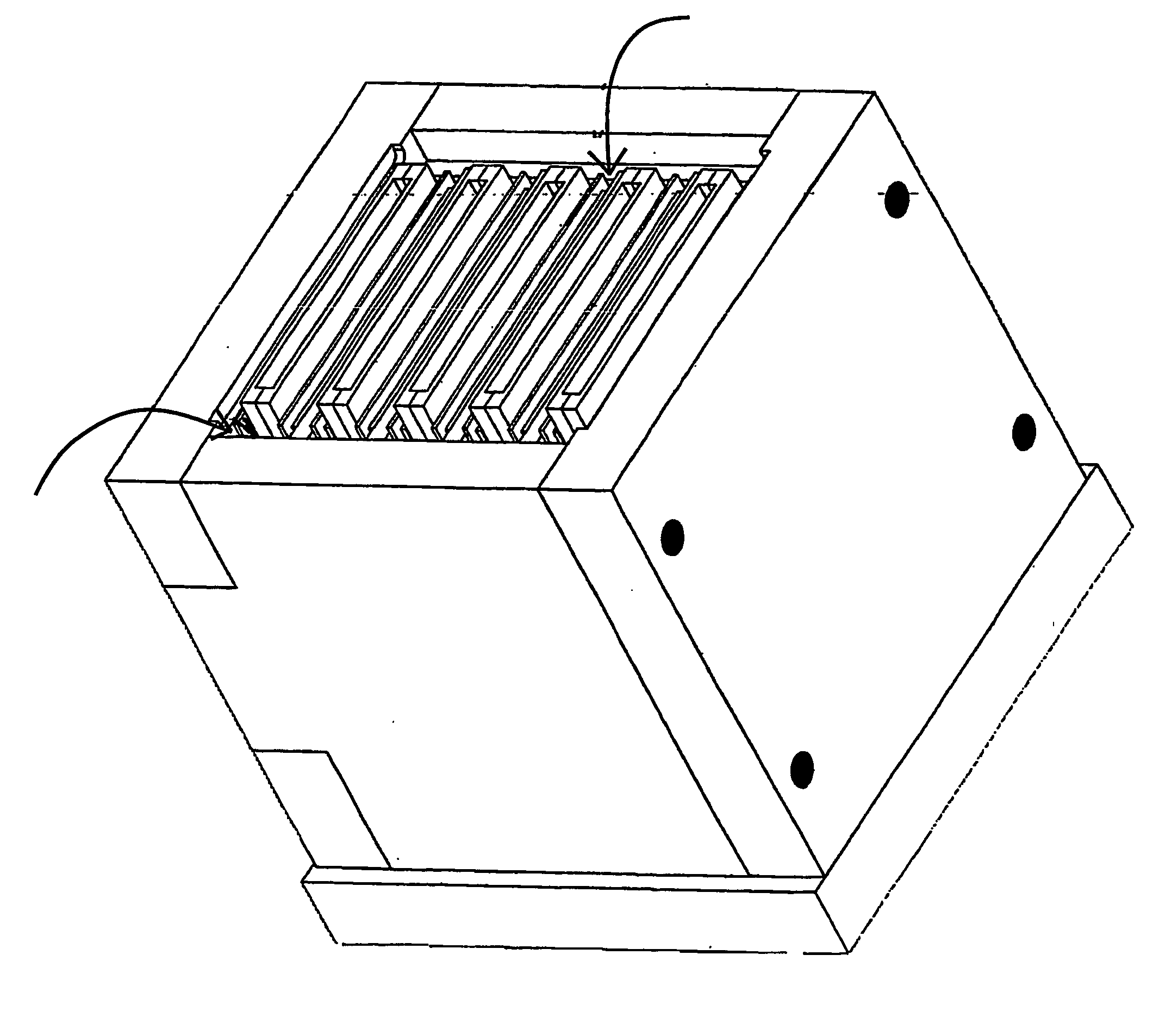
[0033] The present invention is related to a reserve battery, particularly a metal air electrochemical cell in the configuration of a reserve battery. Various novel features are disclosed herein to improve operability and reliability as compared to conventional reserve batteries.

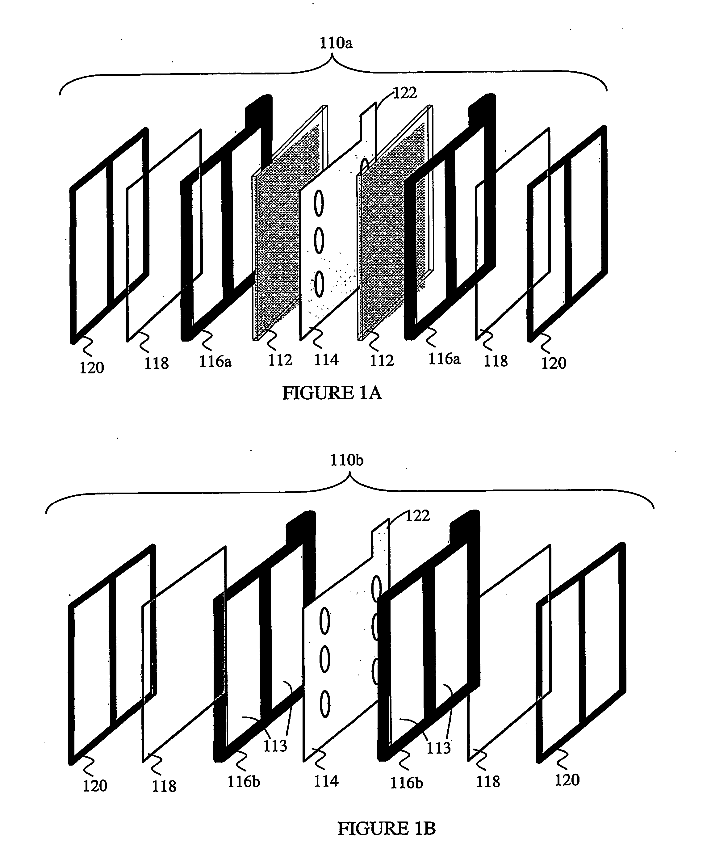
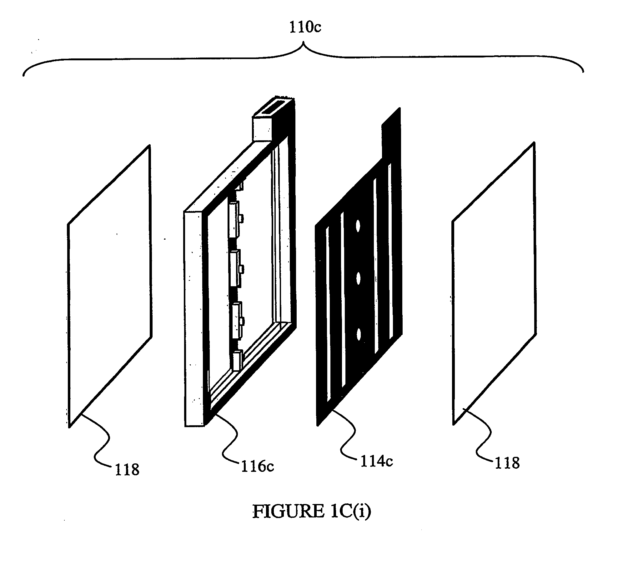
[0034] In general, the reserve metal air electrochemical cell described herein includes a dry component structure including a plurality of dry components. The dry components including an anode (generally a metal fuel anode) and a cathode, particularly an air diffusion cathode. One end of the dry component structure includes a reservoir of electrolyte concentrate. When activation is desired, water or another suitable liquid is added to the reservoir of electrolyte concentrate, whereby diluted electrolyte is introduced into the dry component structure through an electrolyte flow control structure, thereby causing electrochemical reaction between the anode and cathode.

[0035] Having generally described operati...


PUM

PropertyMeasurementUnit
Temperatureaaaaaaaaaa
Pressureaaaaaaaaaa
Flow rateaaaaaaaaaa

Abstract

Provided herein is a structure for use in an electrochemical cell system. The structure includes a dry component housing (180) including a plurality of dry components (110), including an anode (112) and a cathode (132). One end of the dry component housing comprises an electrolyte concentrate (solid or liquid) reservoir (150). The electrolyte concentrate reservoir and the dry components are in fluid communication via a flow control device (170), aperture (172) or system (170a). An electrochemical cell is formed using the structure, in addition to a source (262). When the water is added in the proximity of the electrolyte concentrate reservoir, diluted electrolyte is introduced through an electrolyte flow control device, structure or system, the cell is activated.

Description

BACKGROUND OF THE INVENTION [0001] A reserve battery is one in which electrolyte is maintained in isolation from one or more electrodes of the battery. Thus, the battery is inactive when stored, and activated when the electrodes and electrolyte are brought into ionic contact. Since there is no consumption or reaction with the electrodes under these circumstances, the shelf life is essentially infinite. [0002] For many applications, where a high voltage is required, many batteries are combined to provide the requisite power needs. Moreover, many applications require relatively instantaneous activation. Prior attempts to maintain electrodes and electrolyte out of contact include: structures where one electrode (e.g., zinc) is inserted into a structure with electrolyte and an opposite electrode (e.g., carbon); removing a liner between electrolyte and electrode(s); tilt action of the cell, whereby electrolyte moves into contact with one or more electrodes; pouring or dumping electrolyte...

Claims


Application Information

Patent Timeline
IPC IPC(8): H01M6/32H01M6/36H01M6/38H01M6/50H01M12/06H01M14/00H01M50/77
CPCH01M2/40H01M6/36Y10T29/49108H01M6/50H01M12/06H01M6/38H01M50/77H01M6/32
Inventor MORRIS, WILLIAM F.SOLORZANO, JULIOTSAI, TSEPINLEE, CHENG MINGHSU, AUSTINWAN, LOUISHSU, JIN-HUNGCHU, GARY
Owner MORRIS WILLIAM F
Why Eureka
Try Eureka