Sternal reconstruction system

Active Publication Date: 2005-10-27
SYNTHES GMBH
View PDF45 Cites 20 Cited by
  • Summary
  • Abstract
  • Description
  • Claims
  • Application Information

AI Technical Summary

Benefits of technology

[0021] In one embodiment the at least one flexible cable is attached to a suture. The inner diameter of the at least one ferrule com

Problems solved by technology

One limitation associated with bone screws, however, is that repositioning or adjusting the bone screws following implantation is difficult.
However, as with bone screws, removal of the pins may be required if

Method used


Image

  • Sternal reconstruction system
  • Sternal reconstruction system
  • Sternal reconstruction system

Examples


Embodiment Construction

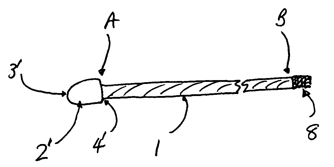
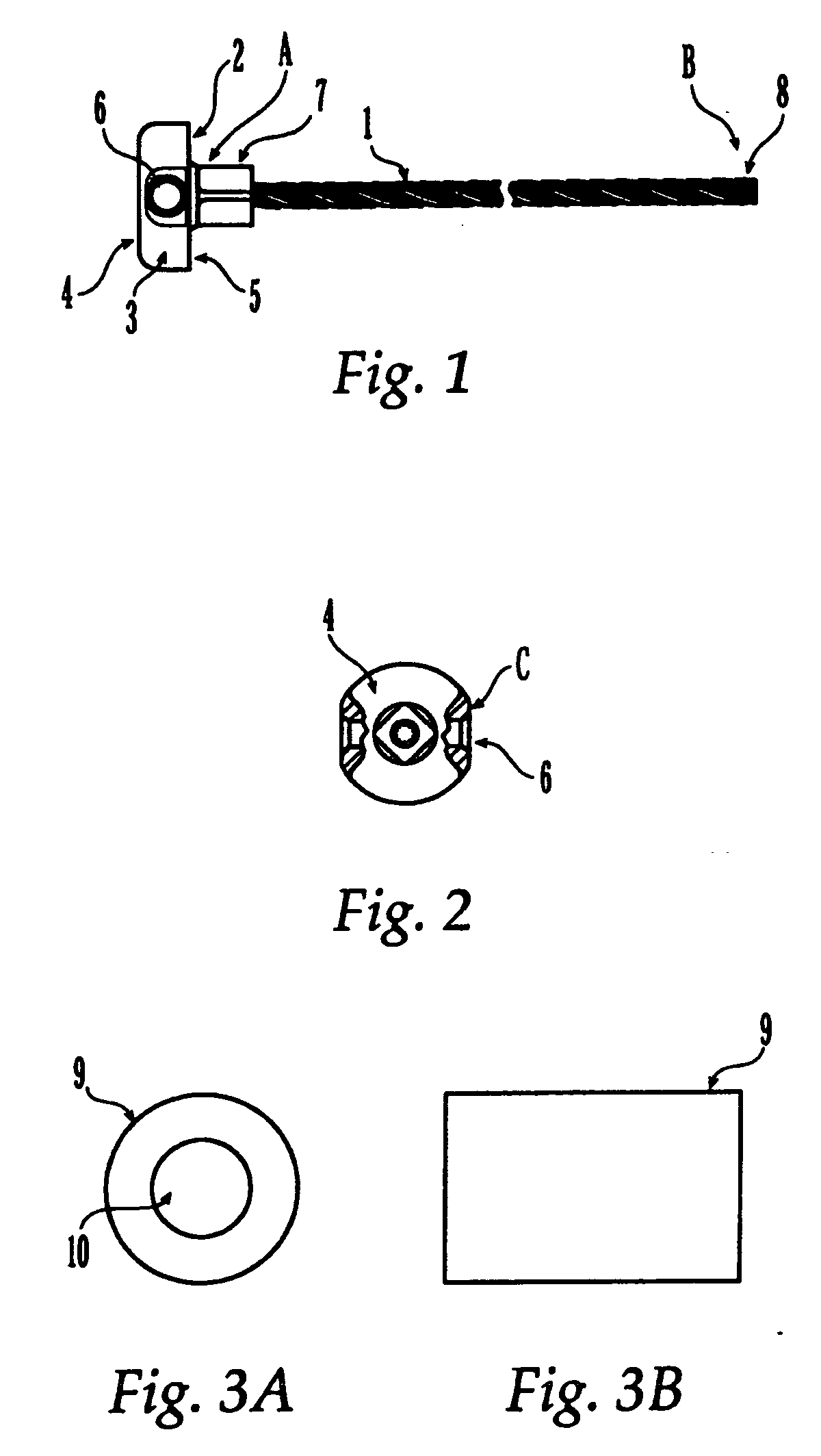
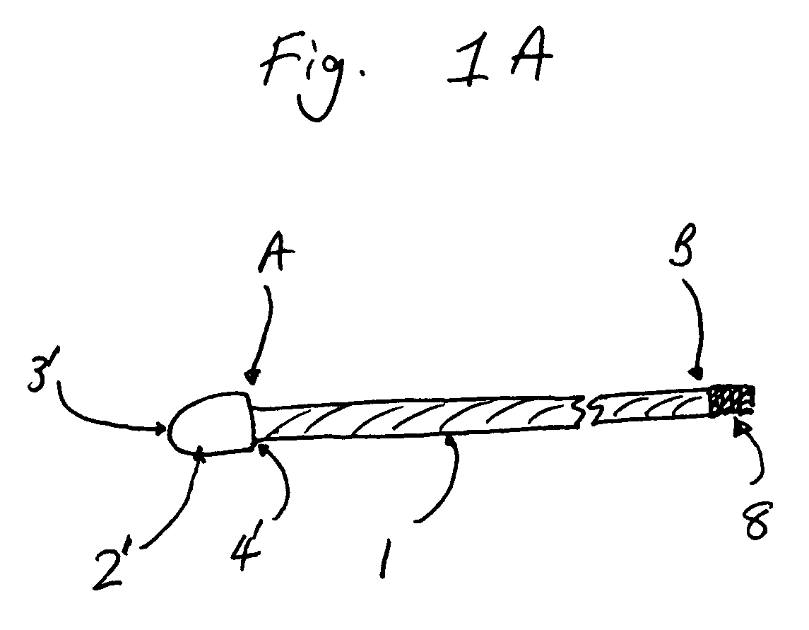
[0041] The sternal reconstruction system of the present invention comprises a flexible cable with crimp, optionally one or more cannulated screws and optionally one or more reconstruction plates. In one embodiment of the present invention, simple circumferential or parasternal fixation may be provided by use of a sternal reconstruction system comprising a flexible cable and ferrule. In another embodiment, fixation may be achieved by use of a sternal reconstruction system comprising a flexible cable, crimp and cannulated screws. In yet another embodiment, fixation may be achieved by use of a sternal reconstruction system comprising a flexible cable, crimp, cannulated screws and one or more reconstruction plates.

[0042] While various descriptions of the present invention are described in the Figures, it should be understood that the various features described are for illustrative purposes, and are exemplary only. Therefore, this invention is not to be limited to only the specifically ...


PUM


Abstract

A sternal reconstruction system for securing parts of a sternum includes at least one flexible cable with a fused end fitting, at least one parallel fitting piece and at least one ferrule. Optionally, the system includes at least one cannulated screw. Circumferential or parasternal fixation may be brought about by use of the sternal reconstruction system. Also provided is a method for sternal reconstruction utilizing the sternal reconstruction system. Also provided is a kit for sternal reconstruction.

Description

[0001] This application claims the benefit of U.S. patent application Ser. No. 10 / 830,130, filed Apr. 21, 2004, the entire disclosure of which is incorporated herein by reference.FIELD OF THE INVENTION [0002] The present invention relates generally to surgical reconstruction systems or devices, and more particularly, to devices for reapproximating two or more parts of a patient's sternum. BACKGROUND OF THE INVENTION [0003] Many surgical procedures require two or more parts of a sternum to be reapproximated, or fixed together, such as sternal reconstruction and repair of sternal trauma. In addition, various types of surgical procedures are currently performed to investigate, diagnose, and treat diseases involving tissues or organs located in a patient's thoracic cavity, such as the heart and lungs. These procedures typically require a partial or median sternotomy to gain access to the patient's thoracic cavity. A partial or median sternotomy is a procedure by which a saw or other app...

Claims


Application Information

Patent Timeline
IPC IPC(8): A61B17/56A61B17/58A61B17/80A61B17/82A61B17/84A61B17/86A61B17/88
CPCA61B17/8076A61B17/823A61B17/8869A61B17/864A61B17/8861A61B17/842A61B17/56A61B17/58A61B17/84
Inventor ALBERTSON, THOMASGOHEEN, CHRISTOPHERMICHELS, MARK
Owner SYNTHES GMBH
Why Eureka
Try Eureka