Pulse detection apparatus, software, and methods using patient physiological signals

a pulse detection and physiological signal technology, applied in the field of cardiac pulse detection in patients, can solve the problems of cardiac arrest, patient's heart failing to provide enough blood flow to support life, and it is extremely difficult for first-responding caregivers with little or no medical training to consistently and accurately detect cardiac pulses

Inactive Publication Date: 2005-10-27
PHYSIO CONTROL INC
View PDF93 Cites 42 Cited by
  • Summary
  • Abstract
  • Description
  • Claims
  • Application Information

AI Technical Summary

Benefits of technology

[0013] In embodiments of the invention that evaluate ECG data, a feature indicative of the presence of a pulse may be determined based on the presence of a Ventricular complex, such as a QRS complex, in the ECG data. Moreover, the presence of a ventricular complex in the ECG data may be used to select time segments of data from one or more of the other physiological signals that correspond in time with the ventricular complex. Identifying and evaluating physiological signal data based on the presence of a ventricular complex helps focus the evaluation of the physiological signal data to that data which are more likely to indicate the presence of a pulse.

Problems solved by technology

Cardiac arrest is a life-threatening medical condition in which the patient's heart fails to provide enough blood flow to support life.
Unfortunately, under the pressures of an emergency situation, it can be extremely difficult for first-responding caregivers with little or no medical training to consistently and accurately detect a cardiac pulse in a patient (e.g., by palpating the carotid artery) in a short amount of time such as 10 seconds.
Nevertheless, because time is of the essence in treating cardiac arrest, a caregiver may rush the preliminary evaluation, incorrectly conclude that the patient has no pulse, and proceed to provide therapy, such as defibrillation, when in fact the patient has a pulse.
Alternatively, a caregiver may incorrectly conclude that the patient has a pulse and erroneously withhold defibrillation therapy.

Method used


Image

  • Pulse detection apparatus, software, and methods using patient physiological signals
  • Pulse detection apparatus, software, and methods using patient physiological signals
  • Pulse detection apparatus, software, and methods using patient physiological signals

Examples


Embodiment Construction

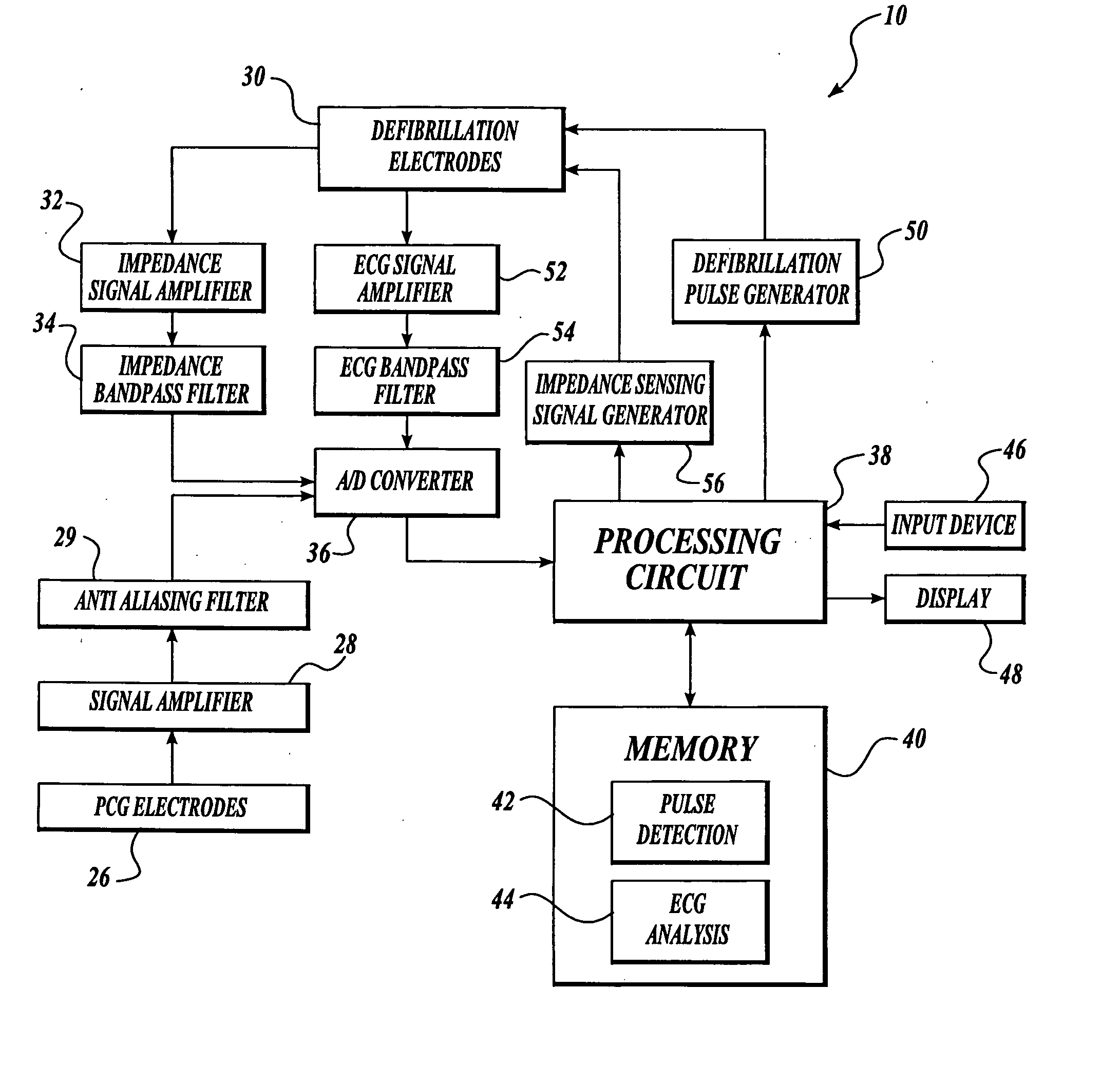
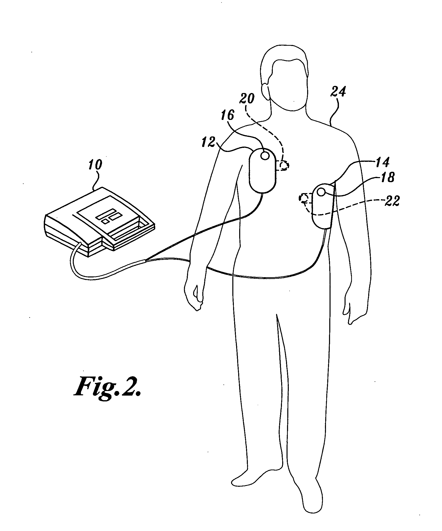
[0045] The present invention may be implemented in a variety of applications. One particular implementation of the present invention is a defibrillator as illustrated in FIG. 2. In FIG. 2, the defibrillator 10 is shown connected to a patient 24 via defibrillation electrodes 12 and 14 placed on the skin of the patient 24. The defibrillator 10 uses the defibrillation electrodes 12 and 14 to deliver defibrillation pulses to the patient 24. The defibrillator 10 may also use the electrodes 12 and 14 to obtain ECG signals from the patient 24.

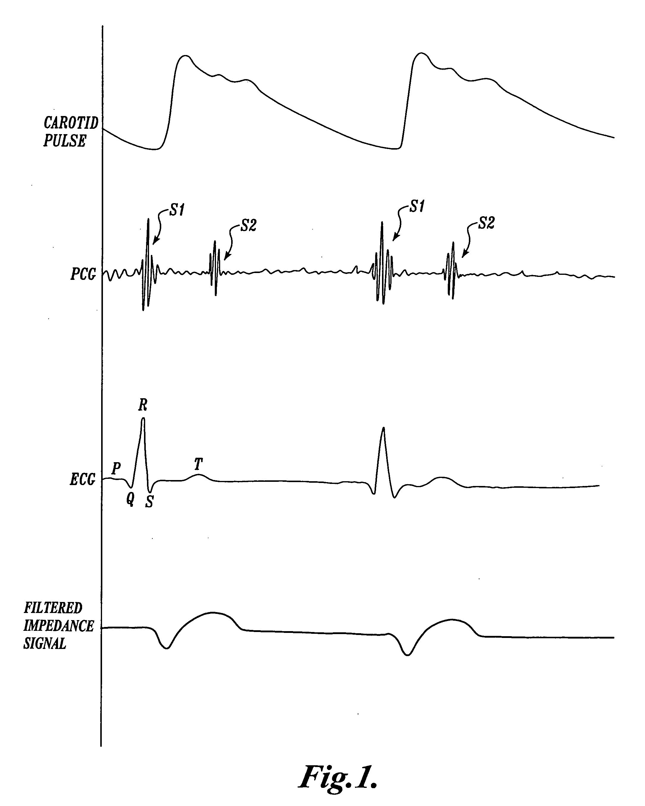
[0046]FIG. 2 further illustrates sensing devices 16 and 18 placed on the patient 24. The sensing devices 16 and 18 are configured to detect a physiological signal in the patient, such as acoustical energy from heart sounds produced in the patient 24 or electrical energy that reflects a patient characteristic such as transthoracic impedance. In one exemplary embodiment discussed herein, the sensing devices 16 and 18 are configured to detect acoustical...


PUM


Abstract

The presence of a cardiac pulse in a patient is determined by evaluating physiological signals in the patient. In one embodiment, a medical device evaluates two or more different physiological signals, such as phonocardiogram (PCG) signals, electrocardiogram (ECG) signals, patient impedance signals, piezoelectric signals, and accelerometer signals for features indicative of the presence of a cardiac pulse. Using these features, the medical device determines whether a cardiac pulse is present in the patient. The medical device may also be configured to report whether the patient is in a VF, VT, asystole, or PEA condition, in addition to being in a pulseless condition, and prompt different therapies, such as chest compressions, rescue breathing, defibrillation, and PEA-specific electrotherapy, depending on the analysis of the physiological signals. Auto-capture of a cardiac pulse using pacing stimuli is further provided.

Description

CROSS-REFERENCE TO RELATED APPLICATIONS [0001] This application is a continuation-in-part of U.S. patent application Ser. No. 09 / 410,198, filed Sep. 30, 1999, and U.S. patent application Ser. No. 10 / 013,941, filed Dec. 6, 2001, priority from the filing dates of which is hereby claimed under 35 U.S.C. § 120.FIELD OF THE INVENTION [0002] The invention relates generally to the detection of cardiac activity in a patient, and more specifically, to the detection of a cardiac pulse and the use of pulse detection in delivering therapy. BACKGROUND OF THE INVENTION [0003] The presence of cardiac pulse, or heartbeat, in a patient is generally detected by palpating the patient's neck and sensing changes in the volume of the patient's carotid artery due to blood pumped from the patient's heart. A graph representative of the physical expansion and contraction of a patient's carotid artery during two consecutive pulses, or heartbeats, is shown at the top of FIG. 1. When the heart's ventricles cont...

Claims


Application Information

Patent Timeline
Patent Type & Authority Applications(United States)
IPC IPC(8): A61B5/025A61B5/0205A61B5/361A61B5/363A61B7/00A61B7/04A61N1/365A61N1/39
CPCA61B5/0464A61B5/0535A61B5/0538A61B5/7264A61N1/3987A61B7/04A61N1/365A61N1/39A61N1/3925A61B7/00A61N1/39044G16H50/20A61B5/363
Inventor JOO, TAE H.STICKNEY, RONALD E.JAYNE, CYNTHIA P.LANK, PAULAO'HEARN, PATRICIAHAMPTON, DAVID R.TAYLOR, JAMES W.CRONE, WILLIAM E.YERKOVICH, DANIEL
Owner PHYSIO CONTROL INC
Why Eureka
Try Eureka