Subsystem replacement method

a subsystem and replacement method technology, applied in the direction of redundant hardware error correction, input/output to record carriers, instruments, etc., can solve the problems of long time-consuming and laborious migration work, severe influence of migration work, and the user's long-term stoppage of disk subsystem operations, so as to avoid failure and replace the old subsystem. , the effect of smooth replacemen

Inactive Publication Date: 2005-10-27
HITACHI LTD
View PDF1 Cites 28 Cited by
  • Summary
  • Abstract
  • Description
  • Claims
  • Application Information

AI Technical Summary

Benefits of technology

[0013] It is an object of the invention to provide a subsystem replacement technique which can continue an access from a higher level device to a subsystem also during switching operation from an old subsystem to a new subsystem.
[0014] It is another object of the invention to provide a subsystem replacement technique which can migrate data in a stopless state of operations without requiring to stop an access from a higher level device to a subsystem in association with data migration.
[0015] It is further another object of the invention to provide a subsystem replacement technique which can smoothly replace an old subsystem operating under the control of a plurality of higher level devices with a new subsystem in a stopless state of operations.
[0016] It is further another object of the invention to provide a subsystem replacement technique which realizes smooth subsystem replacement while avoiding occurrence of a failure caused by a change in environment such as device information in association with replacement of an old subsystem with a new subsystem.
[0027] In the invention, in order to discriminate the access from which one of the plurality of higher level devices and notify the other subsystem of the access, the third access paths of the number equal to or larger than the number of higher level devices connected to the old disk subsystem are provided between the old and new disk subsystems. An access made via the third access path between the disk subsystems is associated with the access from each of the higher level device, thereby enabling the data migration when the old disk subsystem is connected to the plurality of higher level devices to be carried out. The number of the third access paths includes not only the number of physical access paths but also the number of logical access paths.

Problems solved by technology

According to the method, however, operations of the user to the disk subsystem are stopped for a long time during the data migration.
In case of control data of a system such as an OS, even if it is a momentary access stop, it stops the operations of the user and an influence by the migration work is severe.
Especially, the access stop is not accepted by the user where 24-hour online operations are necessary.
The number of such users is increasing and there is a problem such that the data migration cannot be carried out except for the system stop time such as a winter vacation from the end of the year to the beginning of the next year.
When the information of the new subsystem is sent at this time point, since the device information does not match with each other, it is determined that there is a failure in the access path.
Consequently, it is feared that the access path is disconnected and the subsystem becomes down.

Method used


Image

  • Subsystem replacement method
  • Subsystem replacement method
  • Subsystem replacement method

Examples


first embodiment

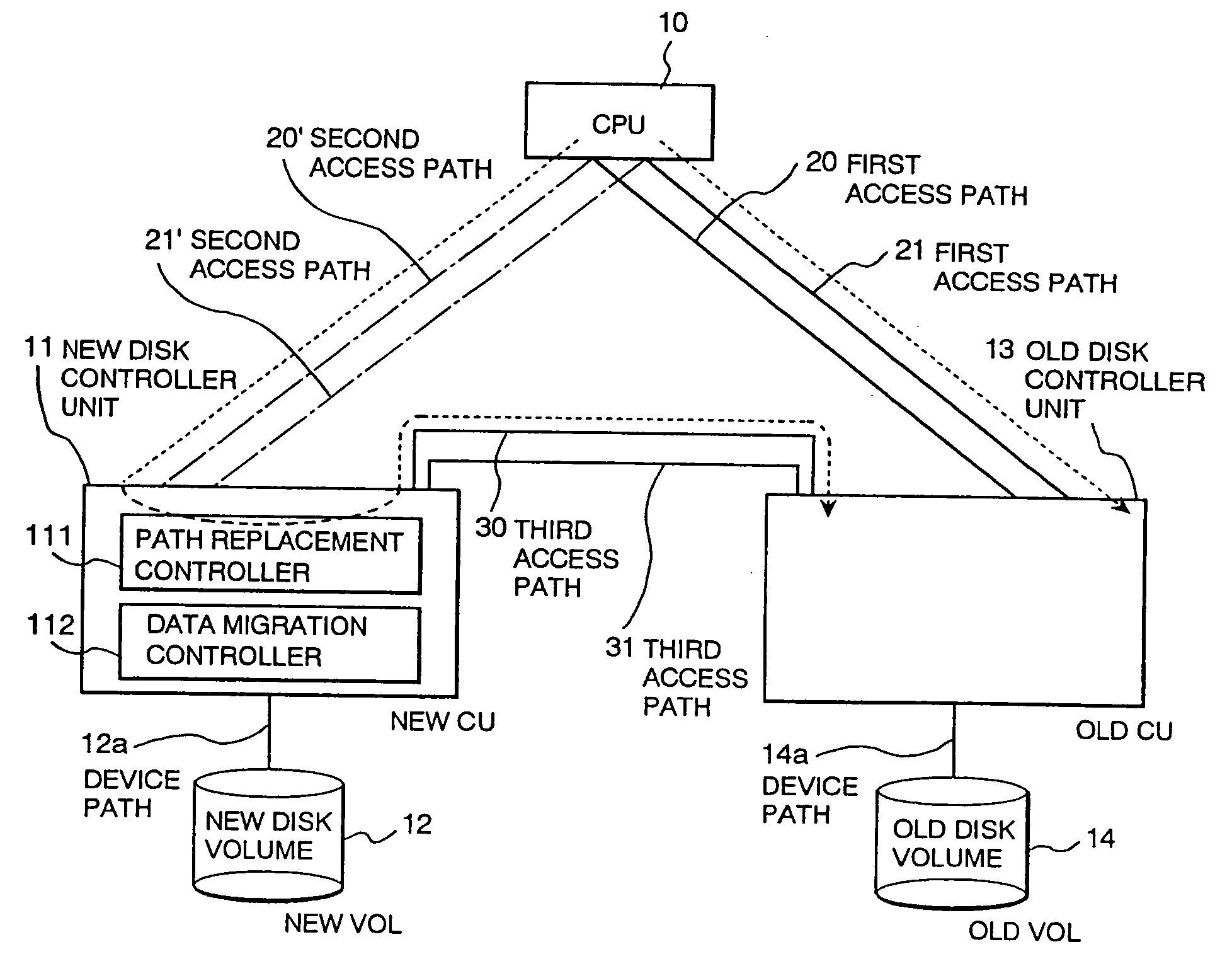
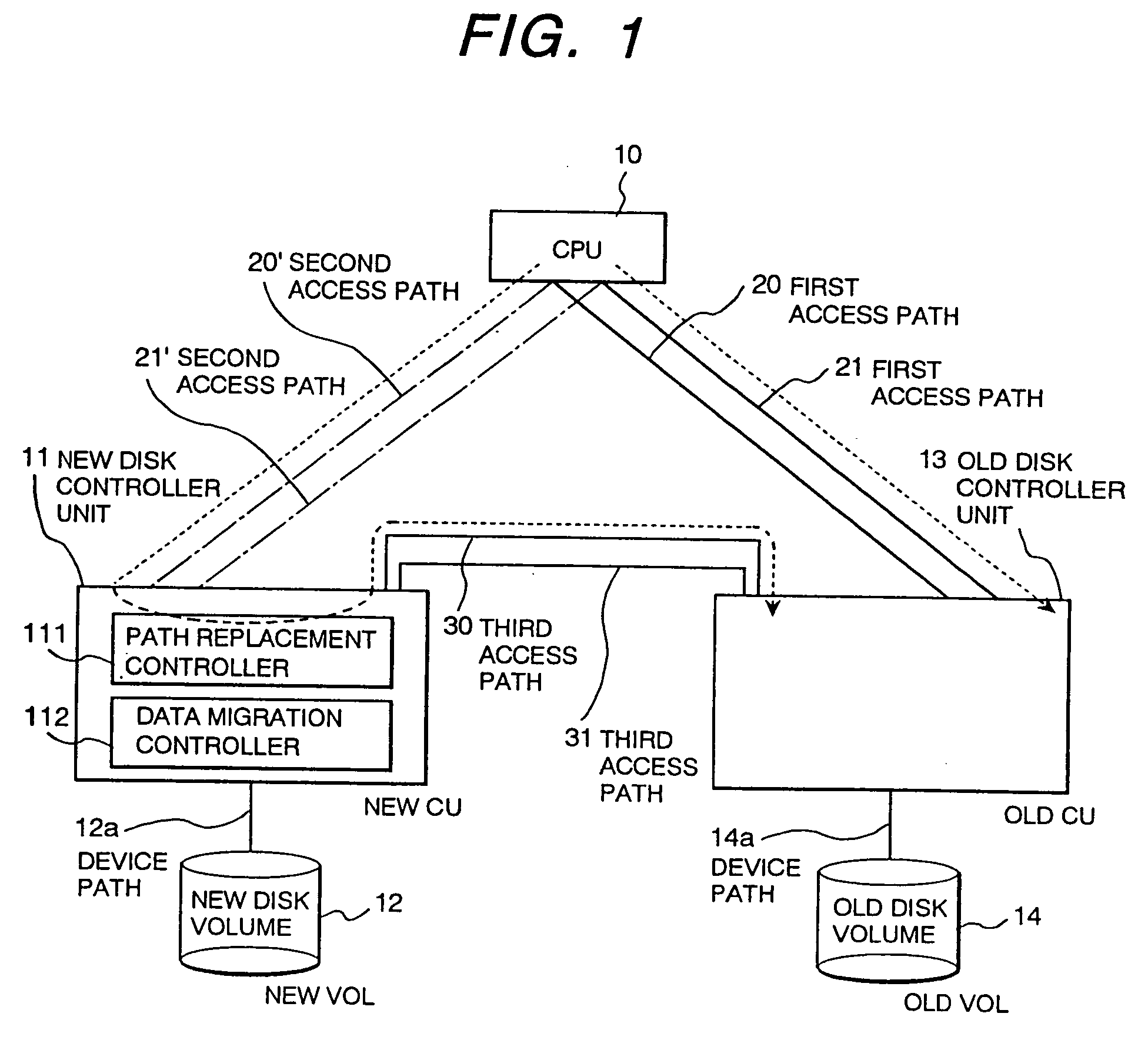
[0041]FIG. 1 is a conceptual diagram showing an example of the configuration and action of a general computer system according to an embodiment of an information processing system to which a subsystem replacement method of the invention is applied.

[0042] According to the embodiment, the general computer system comprises: a central processing unit (CPU) 10; a new subsystem (a new disk subsystem) having a new disk controller unit 11 (hereinbelow, written as “new CU 11”) serving as a destination of data migration and a new disk volume 12 (hereinbelow, written as “new VOL 12”); and an old subsystem (an old disk subsystem) having an old disk controller unit 13 (hereinbelow, described as “old CU 13”) serving as a data migration source and an old disk volume 14 (hereinbelow, described as “old VOL 14”).

[0043] The old VOL 14 is a storage medium operating under the control of the old CU 13 and in which data received from the CPU 10 via the old CU 13 is stored. Likewise, the new VOL 12 is a ...

second embodiment

[0066]FIG. 6 is a conceptual diagram showing another embodiment of the subsystem replacement method of the invention. FIGS. 7 and 8 are flowcharts showing the replacement method.

[0067] The configuration of the information processing system of the embodiment is different from that of the first embodiment with respect to the point that the new CU 11 does not have the path replacement controller and the data migration controller and the old CU 13 is provided with a path replacement controller 131 and a data migration controller 132.

[0068] First, a path switching operation by relaying an access request sent to the old CU 13 through the first access paths 20 and 21 to the new CU 11 via the third access paths 30 and 31 will be described.

[0069] Since the path replacement is executed during an ordinary process, a process by the self CU is designated in the path replacement controller 131. First, third access paths 30 and 31 between the new CU 11 and the old CU 13 are newly installed (ste...

third embodiment

[0078]FIG. 9 shows another embodiment of the invention. The configuration of the embodiment is characterized in that the old CU 13 is also provided with the path replacement controller 131.

[0079] Since the path replacement is not executed during the ordinary process, a process by the self CU is designated in the path replacement controllers 111 and 131. First, third access paths 30 and 31 are newly provided between the new CU 11 and the old CU 13. The path replacement controllers 111 and 131 are designated so as to process an access from the CPU 10 by the self CU and make the same access to the other CU through the third access paths 30 and 31 (the designation will be called hereinbelow a process by both of the CUs). The access from the old CU 13 to the new CU 11 becomes an error since there is no data yet in the new CU 11. There is no problem with a process from the CPU 10 since it is executed by the old CU 13.

[0080] The data replacement controller 112 is instructed to start the ...


PUM


Abstract

A storage system which includes a first storage device, and a storage control device connected to a higher level device and the first storage device. The storage control device controls reading or writing of data from or to the higher level device to or from the storage control device. The storage control device can be connected to another storage control device, and can acquire device information of the other storage control device.

Description

[0001] The present application is a continuation of application Ser. No. 10 / 382,872, filed Mar. 7, 2003; which is a continuation of application Ser. No. 09 / 742,191, filed Dec. 22, 2000; which is a Continuation-In-Part of application Ser. No. 08 / 779,471, filed Jan. 8, 1997, now U.S. Pat. No. 5,978,890 and is a Continuation-In-Part of application Ser. No. 08 / 988,979, filed Dec. 11, 1997, now U.S. Pat. No. 6,230,239; and a divisional of application Ser. No. 09 / 212,410, filed Dec. 16, 1998, now U.S. Pat. No. 6,240,494, the contents of each being incorporated herein by reference.BACKGROUND OF THE INVENTION [0002] The present invention relates to a subsystem replacement technique and, more particularly, to a subsystem replacement operation of a central processing unit in an information processing system which is used on the precondition of stopless operation, or the like. [0003] Data migration denotes a migration of data in an old disk subsystem functioning as an external storage in an in...

Claims


Application Information

Patent Timeline
Patent Type & Authority Applications(United States)
IPC IPC(8): G06F3/06G06F13/14G06F11/14G06F11/20G06F12/00G06F13/10
CPCG06F3/0607G06F3/0647G06F3/0683G06F11/1423G06F11/2071G06F11/2082G06F3/0689
Inventor NAGASAWA, TERUOKOIDE, TAKESHINAKAMURA, KATSUNORI
Owner HITACHI LTD
Why Eureka
Try Eureka