Cutting insert and indexable rotary cutting tool

A cutting edge and blade technology, applied in the field of edge-replaceable turning tools, can solve the problems of increased storage costs, wrong installation of blades, etc., and achieve the effects of shortened replacement work time, smooth replacement, and easy mechanical operations

Inactive Publication Date: 2013-02-27
TUNGALOY CORP
View PDF4 Cites 5 Cited by
  • Summary
  • Abstract
  • Description
  • Claims
  • Application Information

AI Technical Summary

Problems solved by technology

Therefore, when using notched cutting inserts, it is always necessary to prepare multiple types of inserts, leading to an increase in storage costs
In addition, although it is said to be a blade of another shape, the difference is very small, so there is a possibility that a blade other than the type that should be mounted is installed incorrectly, etc.

Method used


Image

  • Cutting insert and indexable rotary cutting tool
  • Cutting insert and indexable rotary cutting tool
  • Cutting insert and indexable rotary cutting tool

Examples


Embodiment Construction

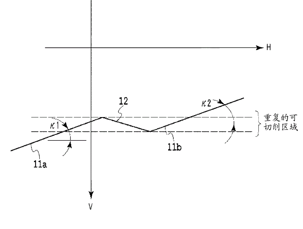
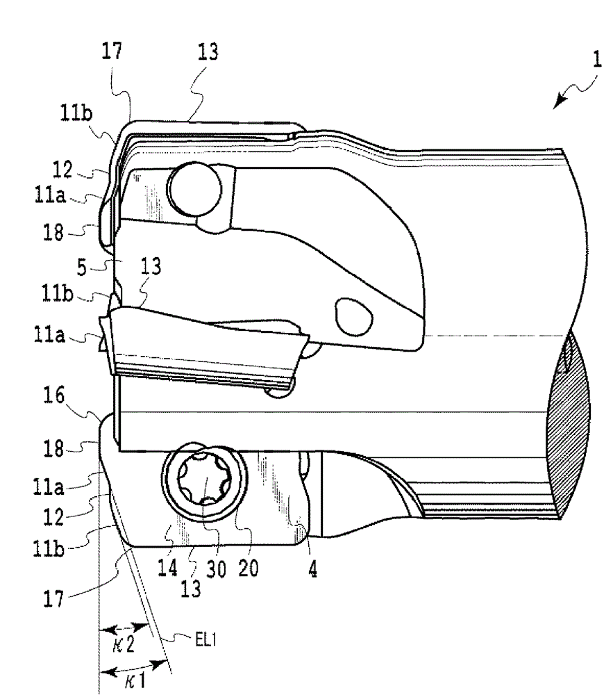
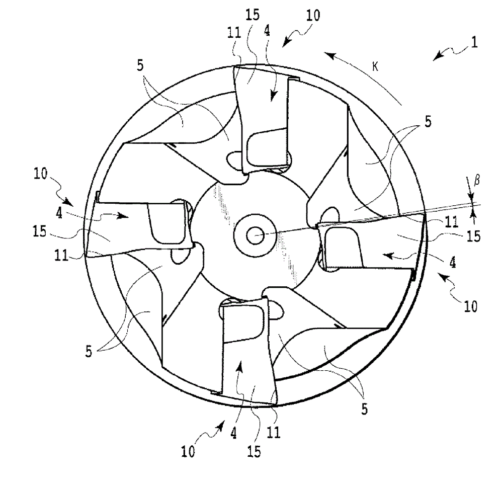
[0028] Hereinafter, an end mill according to an embodiment of the present invention will be described with reference to the drawings. figure 1 It is a front view of the cutting insert used for this end mill. figure 2 as well as image 3 respectively figure 1 Right side view and top view of the cutting insert shown. Figure 4 yes figure 1 X-arrow view. Figure 5 yes figure 1 An enlarged view of the main cutting edge of the cutting insert. Image 6 is a front view of the end mill seen from the axial direction. Figure 7 as well as Figure 8 respectively Figure 5 The right side view and top view of the main part of the shown end mill.

[0029] The cutting insert 10 of this embodiment is as figure 1 As shown, it is in the shape of a substantially parallelogram plate, and among the opposing upper and lower surfaces, a rake surface 14 is formed on the upper surface, a seating surface 19 is formed on the lower surface, and a flank surface is formed on the side extending b...


PUM


Abstract

Provided are a cutting insert suitable for pocket machining of metal molds and the like, and an indexable cutting tool that uses the cutting insert. The cutting insert (10) is provided with: a rake face (14); a flank face (15); and a major cutting edge (11) that is formed on the intersecting ridge of the rake face (14) and the flank face (15), and that extends in the direction that intersects with the cutting direction of the rotary cutting tool. At least one partitioning section (12) that is not involved in cutting is provided in the middle of said major cutting edge (11) in a direction along the major cutting edge (11). The major cutting edge (11) is composed of two first cutting edges (11a) and second cutting edges (11b) separated by the partitioning section (12), and is configured in such a manner that, when the cutting insert is attached to the tool body (1) of the cutting tool, the cutting angles ([kappa]1, [kappa]2) between the first cutting edge (11a) and the second cutting edge (11b) falls in a range of 5 DEG and 20 DEG .

Description

technical field [0001] The present invention relates to a cutting insert and an edge-replaceable turning tool equipped with the cutting insert. Background technique [0002] Conventionally, a turning tool capable of drilling has been used in recess processing in the manufacture of molds and the like. In recess processing, it is one of the conditions for efficient processing to continuously discharge generated chips from the processed recess (recess), and a blower is used for this purpose. In this discharge method, high-pressure air is sprayed onto the machined recess, and the cutting chips are blown out of the hole by the air pressure. [0003] When using a blower, it is not possible to spray high-pressure air to the extent that large chips can be blown away. Therefore, it is required to generate as fine chips as possible for a turning tool for machining recesses. As one of methods for achieving chip refinement, Patent Document 1 discloses a cutting insert in which a plura...

Claims


Application Information

Patent Timeline
Patent Type & Authority Applications(China)
IPC IPC(8): B23C5/20B23C5/10
CPCB23C2200/085B23C2200/205B23C5/20B23C5/205B23C5/207B23C2210/0407B23C5/10B23C5/109Y10T407/1924Y10T407/235B23C5/202B23B2200/208B23C2200/203
Inventor 吉冈史郎
Owner TUNGALOY CORP
Why Eureka
Try Eureka