Fuel supply apparatus for internal combustion engine

a technology for internal combustion engines and fuel supply equipment, which is applied in the direction of liquid fuel feeders, machines/engines, electric control, etc., can solve the problems of pulsation and the disadvantageous fluctuation of the air-fuel ratio, and achieve the effect of reducing the number of pulsations

Inactive Publication Date: 2005-11-03
TOYOTA JIDOSHA KK
View PDF13 Cites 24 Cited by
  • Summary
  • Abstract
  • Description
  • Claims
  • Application Information

AI Technical Summary

Benefits of technology

[0010] The present invention was made in view of the above, and an object of the present invention is to provide a fuel supply apparatus for an internal combustion engine capable of mitigating influence by pulsation generated at least in a high-pressure pump on a quantity of fuel to be supplied to the internal combustion engine.

Problems solved by technology

Consequently, pulsation is produced when the high-pressure pump suctions the fuel from a high-pressure fuel system or when excessive fuel is returned.
Though the ECU controls injection timing and a quantity of fuel to be injected from the port fuel injection valve to the intake port in an intake system of the internal combustion engine in accordance with the operation state of the internal combustion engine, the port fuel injection valve has not been able to inject the fuel of an injection supply quantity, that is, a fuel injection quantity, determined based on the operation state of the internal combustion engine, due to propagation of pulsation to the low-pressure fuel delivery pipe or to the port injection valve.
As described above, the fuel supply apparatus has not been able to supply the fuel of a quantity to be supplied to the internal combustion engine, and an air-fuel ratio representing a ratio between air and the fuel has disadvantageously fluctuated.

Method used


Image

  • Fuel supply apparatus for internal combustion engine
  • Fuel supply apparatus for internal combustion engine
  • Fuel supply apparatus for internal combustion engine

Examples


first embodiment

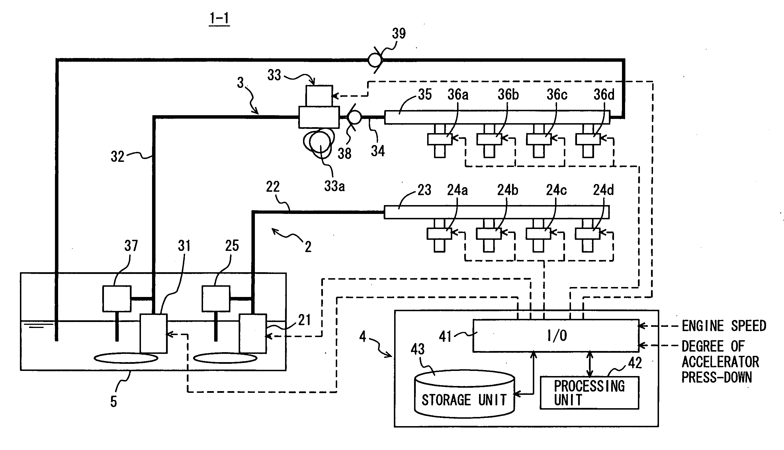
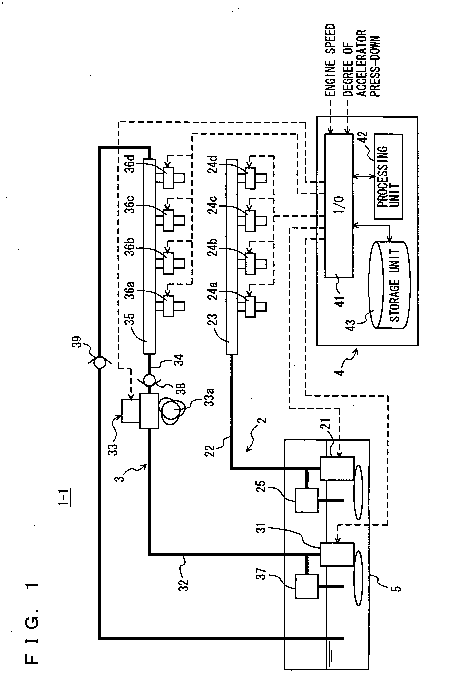
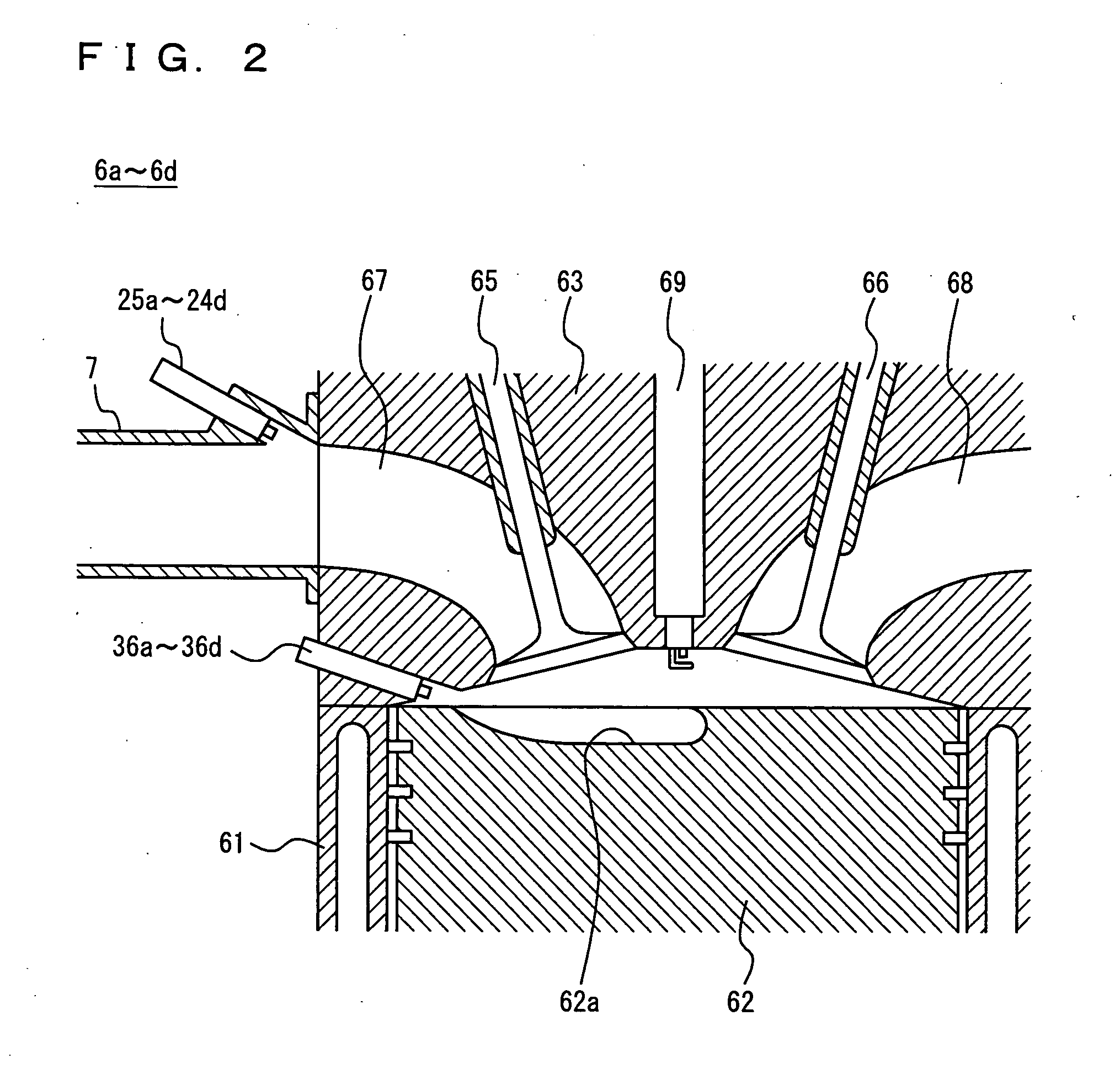
[0032]FIG. 1 illustrates a configuration example of the fuel supply apparatus for the internal combustion engine according to a first embodiment. FIG. 2 illustrates a configuration example of a cylinder of the internal combustion engine according to the present invention. As shown in FIG. 1, a fuel supply apparatus 1-1 according to the first embodiment includes a low-pressure fuel system 2, a high-pressure fuel system 3, an ECU 4, and a fuel tank 5 serving as an accumulator for storing the fuel.

[0033] Low-pressure fuel system 2 is constituted of a first low-pressure pump 21, a first low-pressure pipe 22, and a low-pressure delivery pipe 23 and port fuel injection valves 24a to 24d implementing the low-pressure fuel supply means. A first regulator 25 attains a function as first pressure regulation means for returning a part of the low-pressure fuel discharged from first low-pressure pump 21 to first low-pressure pipe 22 to fuel tank 5 when the pressure of the low-pressure fuel in fi...

second embodiment

[0060] High-pressure pump 33 in high-pressure fuel system 3 operates in the following manner. Cam 33a for the pump rotates, so as to lower a not-shown plunger. Then, a volume in a not-shown pressurizing chamber is increased, and the low-pressure fuel within second low-pressure pipe 32 is suctioned. Thereafter, a not-shown metering valve is closed by ECU 4, the plunger is elevated, and a volume in the pressurizing chamber is decreased. Pressure is then applied to the low-pressure fuel within the pressurizing chamber, and resultant fuel is discharged to high-pressure pipe 34 as the high-pressure fuel. That is, a time period during which the low-pressure fuel within second low-pressure pipe 32 is suctioned by high-pressure pump 33 is half the time period of operation of high-pressure pump 33. Therefore, the discharge flow rate required in second low-pressure pump 31 supplying the low-pressure fuel to high-pressure pump 33 is twice the discharge flow rate (per unit time) of high-pressur...

third embodiment

[0077]FIG. 7 illustrates a configuration example of the fuel supply apparatus according to the third embodiment. Fuel supply apparatus 1-3 shown in FIG. 7 is different from fuel supply apparatus 1-2 shown in FIG. 5 in that an open-close valve 10 is provided instead of check valve 9 provided in connection pipe 8. As a basic configuration of fuel supply apparatus1-3 shown in FIG. 7 is similar to that of fuel supply apparatus 1-2 shown in FIG. 5, description thereof will not be repeated.

[0078] Open-close valve 10 allowing connection between first low-pressure pipe 22 and second low-pressure pipe 32 through connection pipe 8 is provided in connection pipe 8. That is, open-close valve 10 provided in connection pipe 8 serves to open and close connection pipe 8. Opening and closing of open-close valve 10 is controlled by ECU 4. Specifically, open-close valve 10 opens in response to output of an open-close signal from ECU 4, and closes in response to stop of the open-close signal output fr...


PUM


Abstract

A fuel supply apparatus includes: a low-pressure fuel system applying pressure to a fuel in a fuel tank by using a first low-pressure pump and supplying the fuel to port fuel injection valves; a high-pressure fuel system applying pressure to the fuel in the fuel tank by using a second low-pressure pump, applying further pressure to the fuel by using a high-pressure pump driven by an internal combustion engine, and supplying the fuel to in-cylinder fuel injection valves; and an ECU controlling actuation of at least the first low-pressure pump and the second low-pressure pump in accordance with an operation state of the internal combustion engine. As the low-pressure fuel system and the high-pressure fuel system are independent of each other, pulsation generated from the high-pressure pump does not propagate to the port fuel injection valves.

Description

[0001] This nonprovisional application is based on Japanese Patent Application No. 2004-134205 filed with the Japan Patent Office on Apr. 28, 2004, the entire contents of which are hereby incorporated by reference. BACKGROUND OF THE INVENTION [0002] 1. Field of the Invention [0003] The present invention relates to a fuel supply apparatus for an internal combustion engine, and more particularly to a fuel supply apparatus for an internal combustion engine supplying the internal combustion engine with a fuel by using low-pressure fuel supply means and high-pressure fuel supply means. [0004] 2. Description of the Background Art [0005] Examples of a method of supplying a fuel to an internal combustion engine such as a gasoline engine and a diesel engine incorporated in a vehicle such as a passenger car, a truck, or the like include in-cylinder injection for directly injecting the fuel into a combustion chamber within a cylinder of the internal combustion engine, port injection for inject...

Claims


Application Information

Patent Timeline
Patent Type & Authority Applications(United States)
IPC IPC(8): F02B23/10F02M37/00F02B75/12F02D41/02F02D41/04F02D41/34F02D41/38F02M37/08F02M37/18F02M39/00F02M51/00F02M51/04F02M55/02F02M63/02F02M69/00F02M69/04F02M69/46
CPCF02B23/104F02B2075/125F02B2275/16F02D41/3094F02D41/3809F02M69/465F02M37/18F02M63/0225F02M63/029F02M69/044F02M69/046F02D2041/3881
Inventor KOJIMA, SUSUMU
Owner TOYOTA JIDOSHA KK
Why Eureka
Try Eureka