One-way power transmission unit, a fusing unit driving apparatus for duplex printer using the same, a method for one way power transmission, and a method for driving a fusing unit

Active Publication Date: 2005-11-03
HEWLETT PACKARD DEV CO LP
View PDF6 Cites 15 Cited by
  • Summary
  • Abstract
  • Description
  • Claims
  • Application Information

AI Technical Summary

Benefits of technology

[0020] The present invention has been developed in order to solve the above problems in the related art. One of the aspects of the present invention is to provide a one-way power transmission unit and method which are capa

Problems solved by technology

However, it is impossible for the fusing unit to rotate in a backward direction (a paper discharging direction is defined as a forward direction), and thus, when the paper discharging unit rotates in the backward direction to invert a paper sheet, the printing apparatus requires an additional device to prevent the backward driving force from being transmitted to the fusing unit.
However, it is difficult to set an assembly gap between the latch member 30 and the boss 11 of the

Method used


Image

  • One-way power transmission unit, a fusing unit driving apparatus for duplex printer using the same, a method for one way power transmission, and a method for driving a fusing unit
  • One-way power transmission unit, a fusing unit driving apparatus for duplex printer using the same, a method for one way power transmission, and a method for driving a fusing unit
  • One-way power transmission unit, a fusing unit driving apparatus for duplex printer using the same, a method for one way power transmission, and a method for driving a fusing unit

Examples


Example

[0044] It will be understood that like reference numerals refer to like features and structures throughout the drawing figures.

DETAILED DESCRIPTIONS OF THE EXEMPLARY EMBODIMENTS

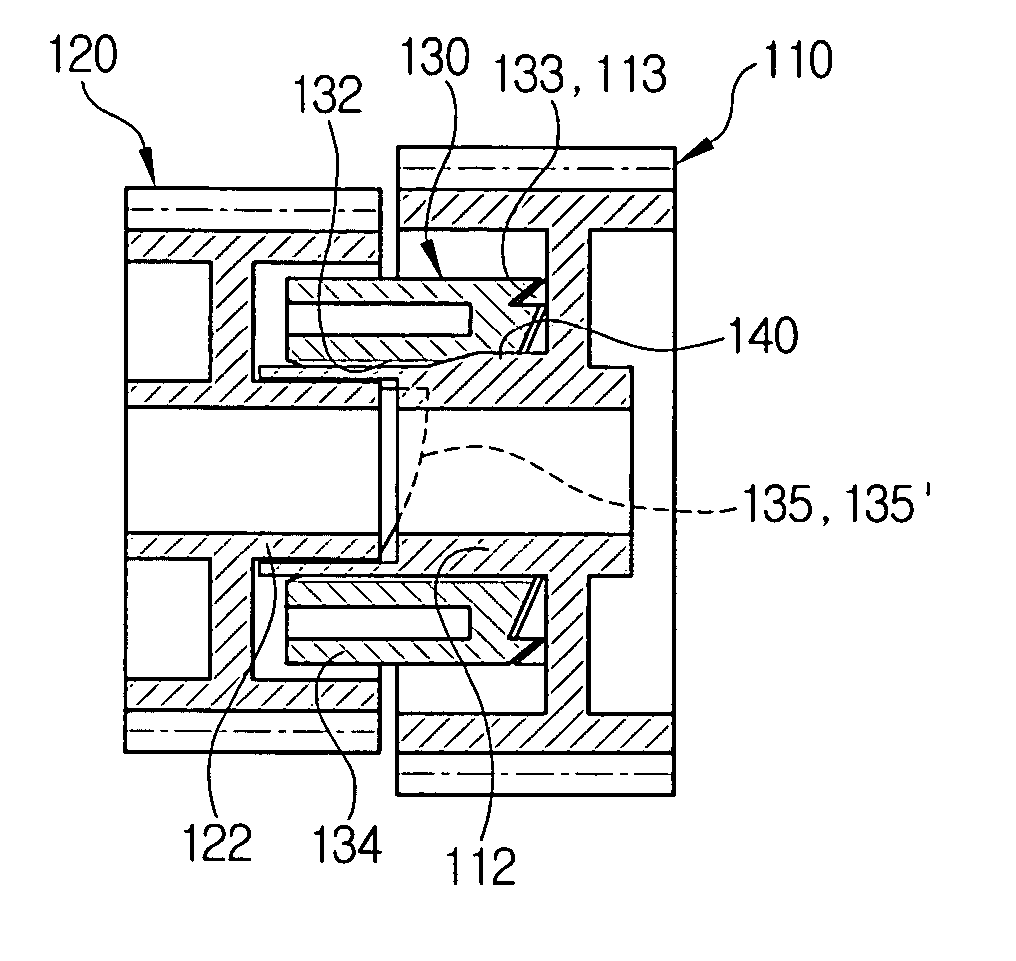
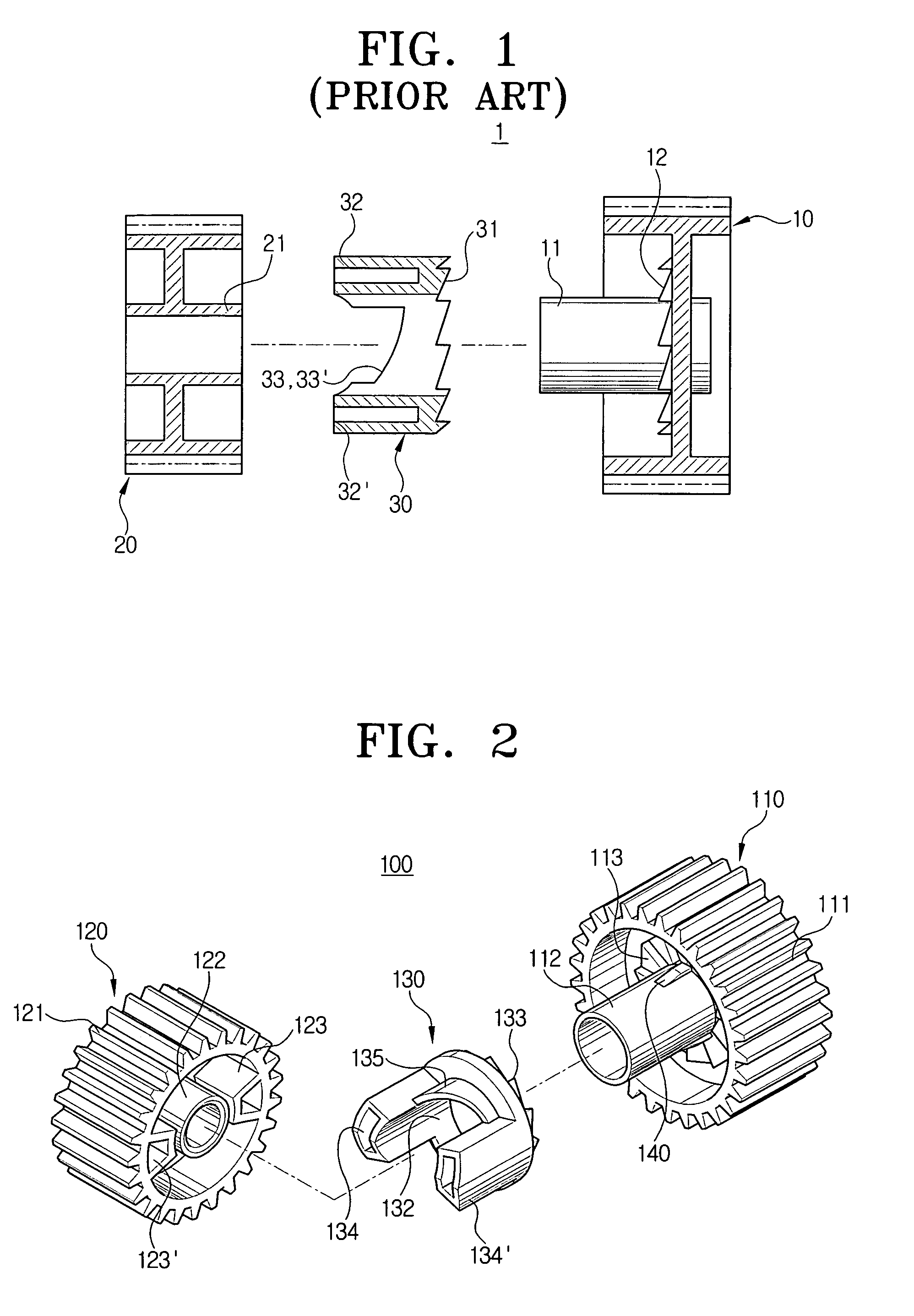
[0045]FIG. 2 is an exploded perspective view showing a one-way power transmission unit 100 according to an embodiment of the present invention. The one-way power transmission unit 100 comprises a driving member 110, a driven member 120, a latch member 130, and a force-fit rib 140 which is one of the features of an embodiment of the present invention.

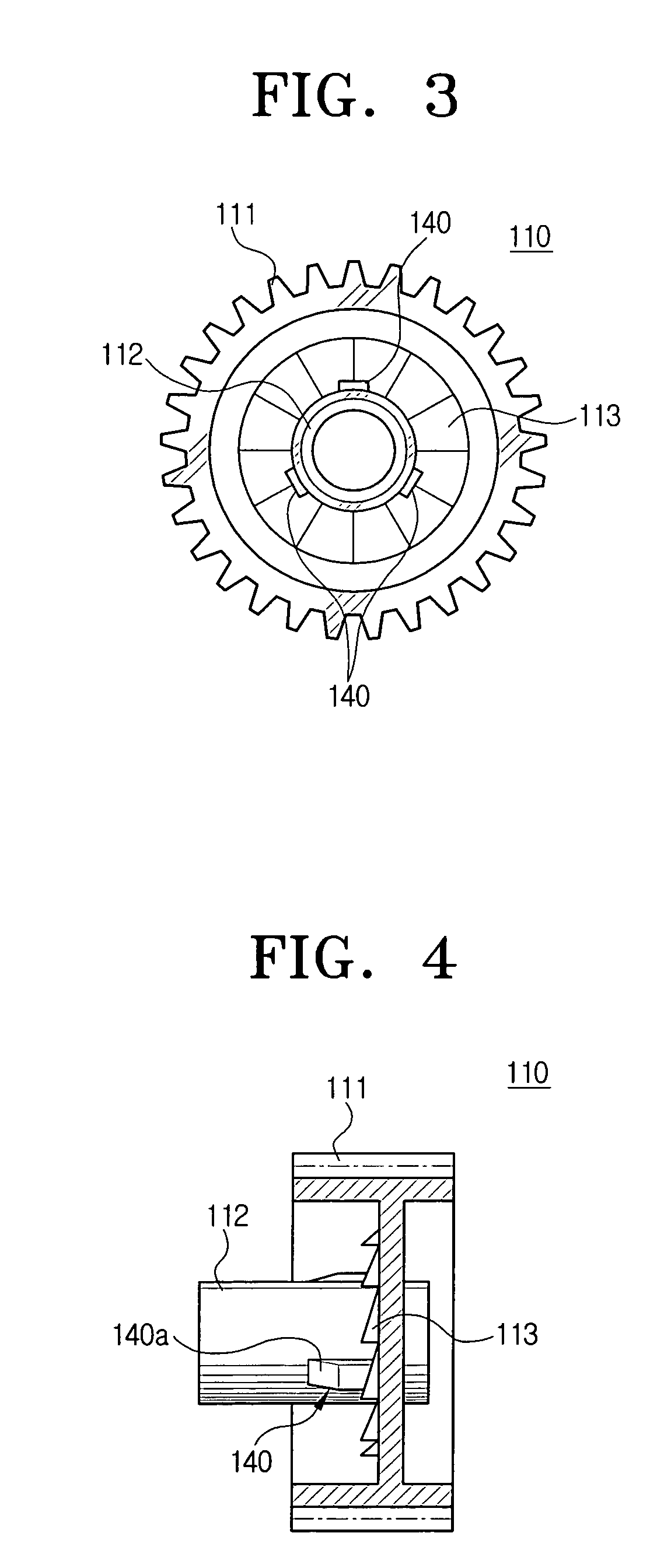
[0046] As shown in FIG. 2, the driving member 110 comprises a gear 111 formed around an outer circumference, a boss 112 formed at a center portion, and a latch gear 113 disposed around the boss 112. The gear 111 may be used for a power transmission mechanism using gear engagement, but it should not be construed as limiting. For example, the gear 111 may be omitted when other types of power transmission mechanism such as a belt, is used.

[0047] The driven member...


PUM


Abstract

A one-way power transmission unit has force-fitting means formed on at least one of an outer circumference of a boss of a driving member and an inner circumference of a boss hole of a latch member, for force-fitting the driving member into the latch member with a friction which is less than a load exerted to a driven member. A method of one-way power transmission including, inter alia, force-fitting the driving member into the latch member with a friction which is less than a load exerted to a driven member. Since the latch member force-fits over the boss of the driving member, the driving member and the latch member rotate together with each other when the driving member switches from a driving force disconnection state to a driving force connection state, and thus, engagement of latch gears of the driving member and the latch member is reliably achieved. Accordingly, the time interval between switching from the driving force disconnection state to the connection state can be maintained to be essentially constant.

Description

CROSS-REFERENCE TO RELATED APPLICATIONS [0001] This application claims the benefit under 35 U.S.C. §119(a) of Korean Patent Application No. 2004-30979, filed on May 3, 2004, in the Korean Intellectual Property Office, the entire disclosure of which is incorporated herein by reference. BACKGROUND OF THE INVENTION [0002] 1. Field of the Invention [0003] The present invention relates to a power transmission unit, and more particularly, the present invention relates to a one-way power transmission unit, and a method, for transmitting only one of a forward driving force and a backward driving force from a driving part to a driven part, a fusing unit driving apparatus for a duplex printer using the same, and a method for driving a fusing unit. [0004] 2. Description of the Related Art [0005] In a mechanism that transmits forward and backward driving forces from one driving part to at least two driven parts, if one driven part requires the forward driving force but the other driven part doe...

Claims


Application Information

Patent Timeline
IPC IPC(8): B41J3/60F16D11/14F16D41/00F16D41/18
CPCF16D41/185H01R9/2408H04Q1/142H04Q2213/13039
Inventor CHA, DOUK-SOON
Owner HEWLETT PACKARD DEV CO LP
Why Eureka
Try Eureka