
Tracking system and methods thereof

a tracking system and tracking technology, applied in the direction of navigation instruments, instruments, electric signalling details, etc., can solve the problems of large gaps in coverage between control points, limited ability of control point systems to resolve the precise location of tracking tags, and many limitations of control point systems

Active Publication Date: 2005-11-03
INTELLECTUAL VENTURES ASSETS 180 LLC
View PDF23 Cites 59 Cited by
  • Summary
  • Abstract
  • Description
  • Claims
  • Application Information

AI Technical Summary

Benefits of technology

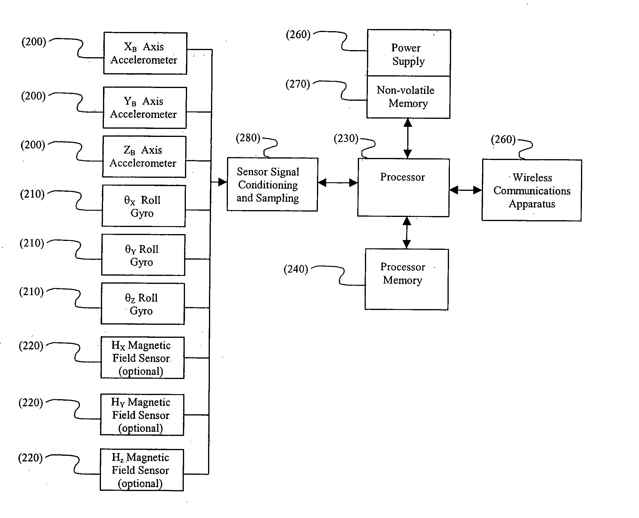
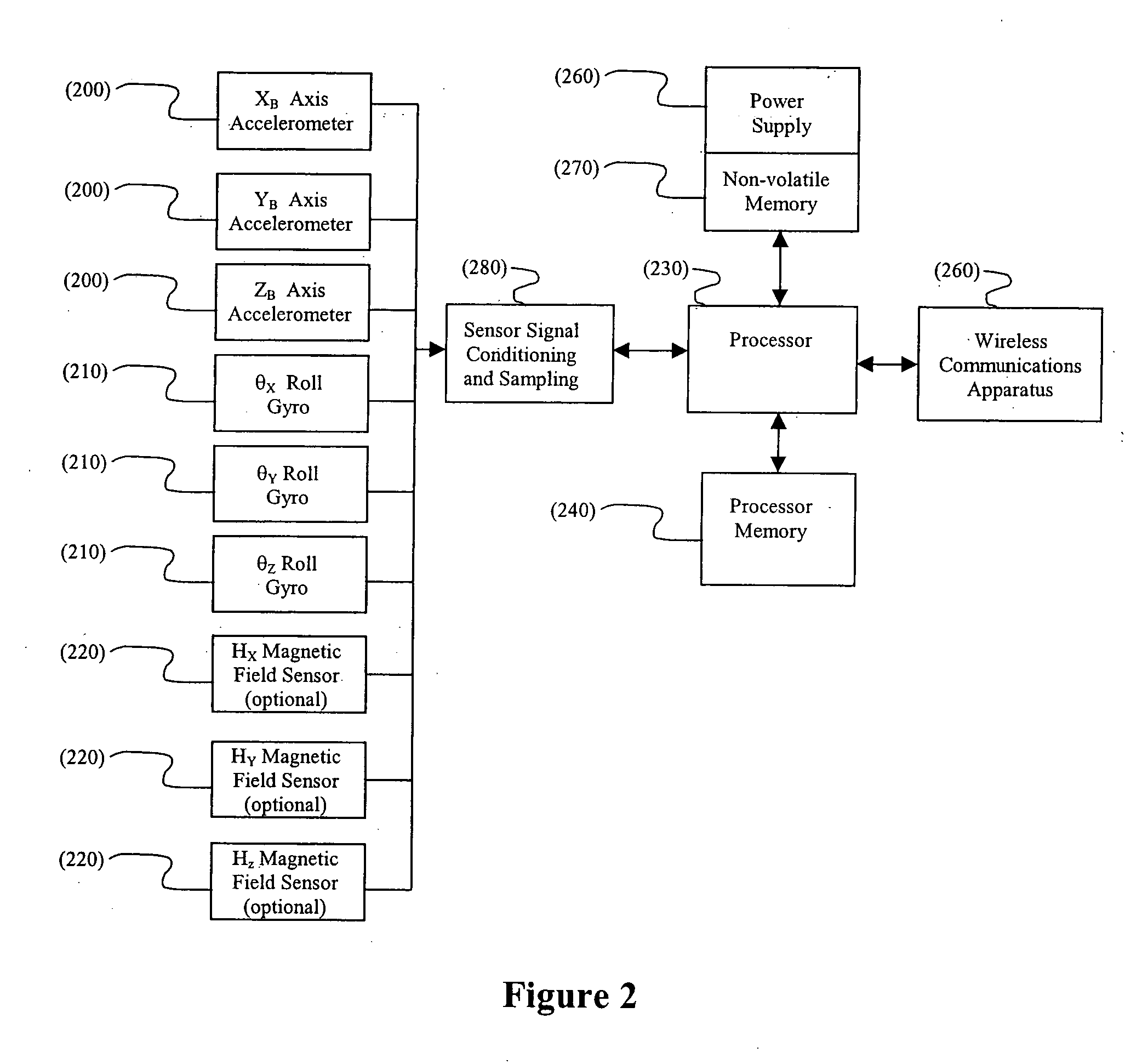
[0012] In certain embodiments, the present invention provides an asset tracking system. In preferred embodiments, the asset tracking system includes at least one tracking device, wherein each tracking device is associated with an asset, wherein each tracking device measures linear acceleration and roll rate, wherein each tracking device determines asset position, and wherein each tracking device detects and reduces measurement error. In other preferred embodiments, the asset tracking system includes a communication network configured to receive said asset position from each tracking device. In some preferred embodiments, the communication network participates in the detection and reduction of measurement error.
[0021] In certain embodiments, the present invention provides an asset tracking system, comprising at least one tracking device associated with an asset, wherein the at least one tracking device measures acceleration and roll rate, identifies and mitigates measurement error, and determines asset position; and a communication network configured to receive the asset position from the at least one tracking device. In further embodiments, the communication network displays the asset position. In other embodiments, the asset is a non-living entity. In other embodiments, the asset is a living entity.
[0026] In certain embodiments, the present invention provides a method of tracking an asset, comprising providing an asset tracking system comprising at least one tracking device associated with an asset, wherein the at least one tracking device measures acceleration, identifies and mitigates measurement error, and determines asset position; and a communication network configured to receive the asset position from the at least one tracking device; and acquiring the asset position for each asset.
[0030] In certain embodiments, the present invention provides a method of tracking an asset, comprising providing a tracking device associated with an asset and an initial reference position, wherein the tracking device is configured to measure linear acceleration and roll rate, wherein the tracking device is configured to mitigate measurement error associated with the linear acceleration and roll rate measurements, wherein the tracking device is configured to determine the position of the asset; acquiring the linear acceleration and roll rate measurements; mitigating the measurement errors associated with the linear acceleration and roll rate measurements, and determining the position of the asset in relation to the initial reference position.

Problems solved by technology

There are several limitations to control point systems as they relate to asset tracking.
The ability of the control point system to resolve the precise location of a tracking tag is limited.
In addition, there are large gaps in coverage between control points due to the propagation characteristics of IR and RF signal energy.
There are several limitations to time of arrival systems as they relate to asset tracking.
Another set of limitations arises from the reflective nature of radio wave propagation.
Multipath reflections can substantially increase the time of arrival for radio signals which will degrade the accuracy of any such system.
Multipath reflections are especially problematic in an indoor environment.
Another problem with time of arrival systems is that their accuracy is a function of the spatial diversity and number of time-of-arrival paths that can be determined.
This limits the useful coverage area of a system to those areas where a transmitting tracking tag is within range of a minimum of three reference receivers.
There are several limitations to the GPS system as it relates to asset tracking.
The primary limitation is that GPS signals do not penetrate buildings and therefore assets in places such as hospitals and factories can not be located with GPS.
A limitation with this tracking system is it provides no means of mitigating sensor errors inherent to all inertial sensor techniques such as noise, drift, error in calibration factors, and mechanical alignment errors.

Method used


Image

  • Tracking system and methods thereof
  • Tracking system and methods thereof
  • Tracking system and methods thereof

Examples


Embodiment Construction

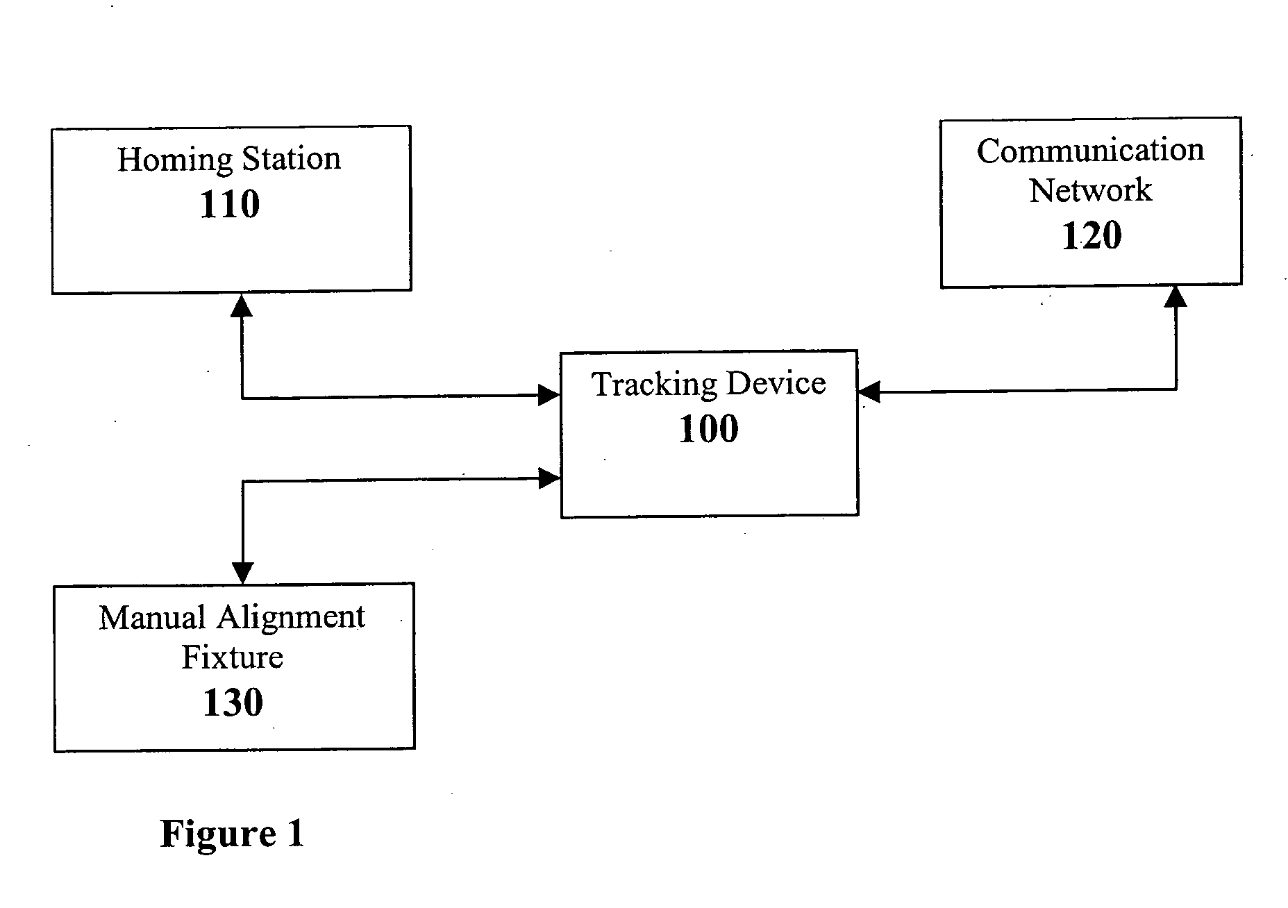
[0052] The present invention provides tracking systems and methods for monitoring the location of an asset or group of assets. In particular, the present invention provides systems for monitoring the location of each member of a large group of assets. Furthermore, the present invention provides systems and methods for uniquely identifying a particular asset within a group of assets. The illustrated and preferred embodiments discuss these systems and methods. These systems and methods are well suited for use with any type of asset tracking within any type of setting. FIGS. 1-7 show various preferred embodiments of the tracking device systems and methods of the present invention. The present invention is not limited to these particular embodiments.

[0053]FIG. 1 presents a schematic of the present invention, and includes a tracking device 100, a homing station 110, a communication network 120, and a manual alignment fixture 130. Generally, a tracking device 100 receives initial positio...


PUM


Abstract

The present invention relates generally to tracking systems and methods for monitoring the location of an asset or group of assets. In particular, the present invention provides systems for monitoring the location of a large group of assets. Furthermore, the present invention provides systems and methods for identifying an asset within a group of assets.

Description

FIELD OF THE INVENTION [0001] The present invention relates generally to tracking systems and methods for monitoring the location of an asset or group of assets. In particular, the present invention provides systems for monitoring the location of each member of a large group of assets. Furthermore, the present invention provides systems and methods for uniquely identifying a single asset within a group of assets. BACKGROUND OF THE INVENTION [0002] A variety of methods and systems exist for tracking and locating assets and personnel in a facility such as a hospital or a factory. Present tracking methods currently available fall into several broad categories of operation: 1) control point; 2) time of arrival; and 3) GPS. [0003] In control point schemes asset tracking tags are affixed to assets to be tracked. One such control point approach is presented in U.S. Pat. No. 6,344,794. Other control point methods are based on RFID technology similar to the system marketed by AXCESS Inc. The...

Claims


Application Information

Patent Timeline
Patent Type & Authority Applications(United States)
IPC IPC(8): G01C21/00G08B1/08
CPCG01C21/005G08B13/2485G08B13/2462
Inventor BURNESKE, GREGORY W.SCHLEIFER, FRED F.
Owner INTELLECTUAL VENTURES ASSETS 180 LLC
Learn More