Resilient packet ring device

Inactive Publication Date: 2005-11-03
FUJITSU LTD
View PDF15 Cites 32 Cited by
  • Summary
  • Abstract
  • Description
  • Claims
  • Application Information

AI Technical Summary

Benefits of technology

[0047] Also, another object of the present invention is to provide an RPR device that can reduce a cost of the entire device.
[0048] Also, another object of the present invention is to provide an RPR device th

Problems solved by technology

However, in the network establishment using the private line, in an end-to-end communication, the following problems occur.
Also, because of its system in which the price of services are determined on the basis of a connection distance of the private line, the construction of a national network based on the private

Method used


Image

  • Resilient packet ring device
  • Resilient packet ring device
  • Resilient packet ring device

Examples


modified example

[0271] The configuration of the RPR device explained by referring to FIG. 2 to FIG. 5 can be modified as explained below.

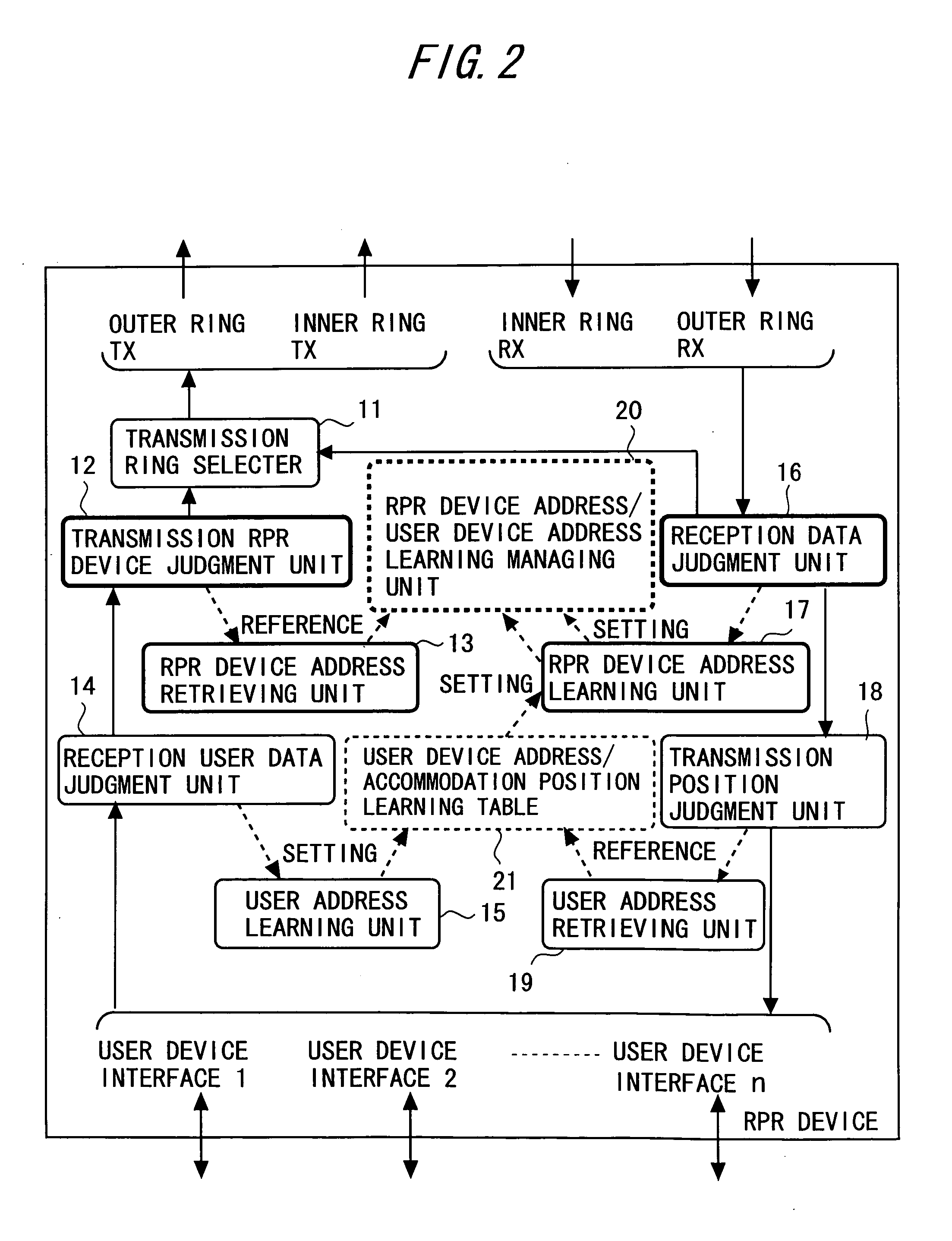
[0272] In the above-mentioned operations, the reception data judgment unit 16, if the destination RPR device address of the RPR header of the RPR data packet is addressed to the RPR device ifself, passes the RPR data packet to the transmission position judgment unit 18 and the RPR device address learning unit 17, and if the destination RPR device address is the broadcast address, passes the RPR data packet to the transmission ring selector 11, the transmission position judgment unit 18 and the RPR device address learning unit 17, and if the destination RPR device address is the RPR data packet other than them, passes to the transmission ring selector 11 and the RPR device address learning unit 17.

[0273] That is, the reception data judgment unit 16, if the RPR data packet should be captured by its own device, is configured so as to pass this RPR data packet to th...

embodiment

[Embodiment]

[0287] An embodiment of the present invention will be described below. The phrases used in the following embodiment are explained below.

[0288] The “ring topology information” includes information on the MAC address of the RPR device existing on the ring network, the number of hops from the self-RPR device, and the like.

[0289] The “Topology Map” means the table storing the ring topology information collected in the topology detection.

[0290] The “VLAN ID” is the identifier for identifying VLAN (Virtual LAN), and a unique value in the layer 2 network, and corresponds to the above-mentioned “L2 Grouping Identifier”.

[0291] The “RPR data packet” is the packet (MAC frame) to which the RPR header is added. In the RPR ring network, the packet (MAC frame) from the outside of the ring is encapsulated on the basis of a format (including the RPR header) in accordance with the RPR, and transferred on the ring.

[0292] The RPR header includes: the MAC address of the RPR device of th...

first operation example

Case of Using No L2 Grouping Identifier

[0305] At first, as the first operation example in the embodiment, the operations of the respective RPR devices 1 to 6 until the time when the user device E receives the packet transmitted by the user device A as shown in FIG. 6 are explained with regard to the case of using no L2 grouping identifier. Among the respective RPR devices 1 to 6, at least the RPR devices 4, 5, and 6 have the configurations and functions shown in FIG. 2.

[0306] Each of the RPR devices 1 to 6 on the ring network learns the connection configuration inside the ring by using the topology detection function that is the existing RPR technique. Each of the RPR devices 1 to 6 broadcast-transmits the topology detection message, in order to perform the topology detection on the inner ring and the outer ring. The topology detection message has the format shown in FIG. 10. The RPR header of the topology detection message at this time has the set value shown in FIG. 11.

[0307] F...


PUM


Abstract

A resilient packet network (RPR) device is connected to one or more rings to constitute an RPR network. The RPR device has a storage unit in which a correspondence between RPR device addresses, each indicating an RPR device connected to the one or more rings, and user device addresses, each indicating a user device accommodated in the RPR device, is stored. When the RPR device receives data addressed to a predetermined user device from a user device accommodated in the RPR device itself, if an RPR device address of an RPR device accommodating the predetermined user device is registered in the storage unit, an RPR header, in which the RPR device address is set as a destination RPR device address, is added to the data. The data with the RPR header is transmitted to the RPR network.

Description

BACKGROUND OF THE INVENTION [0001] 1. Field of the Invention [0002] The present invention relates to an RPR (Resilient Packet Ring) network constituted in such a way that a plurality of RPR devices are connected to one or more rings, and more particularly to a packet transfer method using an RPR technique that uses an L2-RPR mapping table in a layer 2 (L2, namely datalink layer in OSI reference model) [0003] 2. Description of the Related Art [0004] Conventionally, in a connection between remote hosts, network construction using a private line was a typical method. However, in the network establishment using the private line, in an end-to-end communication, the following problems occur. [0005] (1) This results in the occupation of all bandwidths. [0006] (2) A price is set high in various services such as private line IP (Internet Protocol) connection and the like. [0007] Also, because of its system in which the price of services are determined on the basis of a connection distance of...

Claims


Application Information

Patent Timeline
IPC IPC(8): H04L12/437H04L12/46H04L12/70H04L29/06H04L29/12
CPCH04L12/437H04L29/12009H04L29/12584H04L69/22H04L61/2596H04L61/6022H04L29/12839H04L61/00H04L2101/622
Inventor HIGASHITANIGUCHI, ATSUKOKONOSHITA, HIROSHITOKUNAGA, AKIRASHIMIZU, YOSHIHIRO
Owner FUJITSU LTD
Why Eureka
Try Eureka