Clip

a technology of resin and clips, applied in the direction of screws, threaded fasteners, snap fasteners, etc., can solve the problems of affecting the stability of the clip, the position of the fitting hole cannot be easily confirmed by a worker, and the prying force (a diagonal pulling force) may be exerted on the clip, so as to prevent the backlash of the fitting member or the disengagement of the clip. , the effect of stabilizing the locking for

Inactive Publication Date: 2005-11-03
PIOLAX CO LTD
View PDF21 Cites 75 Cited by
  • Summary
  • Abstract
  • Description
  • Claims
  • Application Information

AI Technical Summary

Benefits of technology

[0011] An object of the invention is to provide a clip in which collapse or break of engaging pieces is unlikely to occur, even though a leg part of the clip has been diagonally inserted into a fitting hole or a prying force has been applied to the clip, and more stabilized locking force can be obtained.
[0014] Moreover, the clip according to the invention has the at least three projections which are radially extended from the post in a diametrical direction and connected to the lower face of the head part at their upper ends. Therefore, even though the leg part has been diagonally inserted into the fitting hole or a prying force has been exerted on the clip, eccentricity of the leg part with respect to the fitting hole will be restricted within a determined range by means of the at least three projections, and the engaging pieces can be prevented from being excessively flexed, to be collapsed or broken. Further, because the at least three engaging pieces arranged between the respective projections are engaged with the peripheral edge of the fitting hole at the back side thereof, the clip will be unlikely to be inclined, even though the prying force has been exerted, and consequently, disengagement of the clip can be prevented.
[0015] Still further, the engaging pieces are connected to the head part at their upper ends, and the determined slits are formed between the circumferentially extended ends of the engaging pieces and the projections opposed thereto. Because the lower ends of the engaging pieces are connected to the opposed projections, and are not perfect free ends, the engaging pieces will be prevented from being collapsed or broken, even though they are pressed with the inner periphery of the fitting hole to receive an excessive flexing force. In addition, in a state engaged with the back face of the fitting hole, a stabilized locking force can be obtained, and a backlash of the fitting member and disengagement of the clip can be prevented.
[0017] According to the above described invention, when the leg part is inserted into the fitting hole, the lower ends of the projections which are reduced in diameter in a taper shape will enter into the fitting hole thereby to guide the insertion. Therefore, in case of fitting the door trim for example, the leg part of the clip can be easily inserted into the fitting hole in the body panel, even in case where the fitting hole is hidden behind the door trim and cannot be seen.
[0020] As described above, according to the invention, even though the leg part of the clip has been diagonally inserted into the fitting hole or the prying force has been exerted on the clip, collapse or break of the engaging pieces will be unlikely to occur. Accordingly, stabilized locking force can be obtained, and a backlash of the fitting member or disengagement of the clip can be prevented.

Problems solved by technology

However, the leg part of the clip is likely to be displaced from the fitting hole due to assembling variations when the vehicle has been assembled, and a position of the fitting hole cannot be easily confirmed by a worker, after the body panel has been covered with the door trim.
Moreover, there has been such a trouble that a prying force (a pulling force in a diagonal direction) may be exerted on the clip, even after the door trim and the body panel have been assembled together, due to variations or distortions in molding them.
When the leg part has been diagonally inserted, or the prying force has been applied to the clip in this manner, it has sometimes happened that a particular one of the elastic engaging pieces is excessively flexed, and exceeds a limit of elasticity of the elastic engaging piece, resulting in collapse or break of the particular elastic engaging piece.
Consequently, it has sometimes happened that a sufficient locking force with respect to the fitting hole cannot be obtained, and the clip may cause a backlash or may be disengaged.
Accordingly, there has been such probability that in case where a local pressure has been applied to the engaging pieces when they have been diagonally inserted, a particular engaging piece may be excessively flexed to cause plastic deformation, and engaging ability may be deteriorated.
Accordingly, there has been such a problem that the connecting portions may be likely to be broken.

Method used


Image

  • Clip
  • Clip
  • Clip

Examples


Embodiment Construction

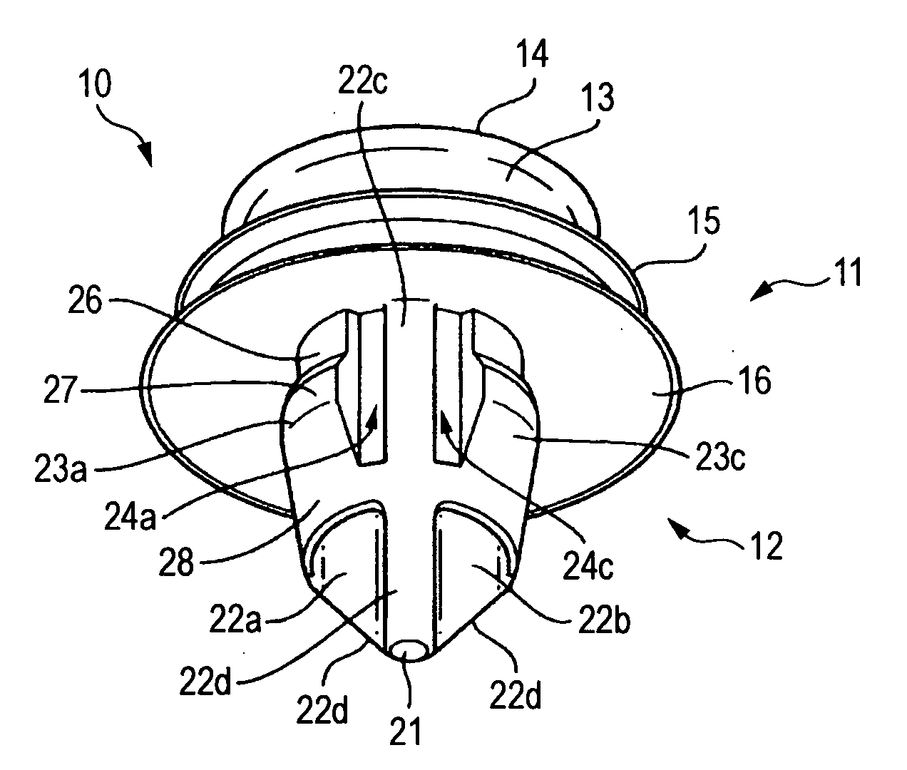
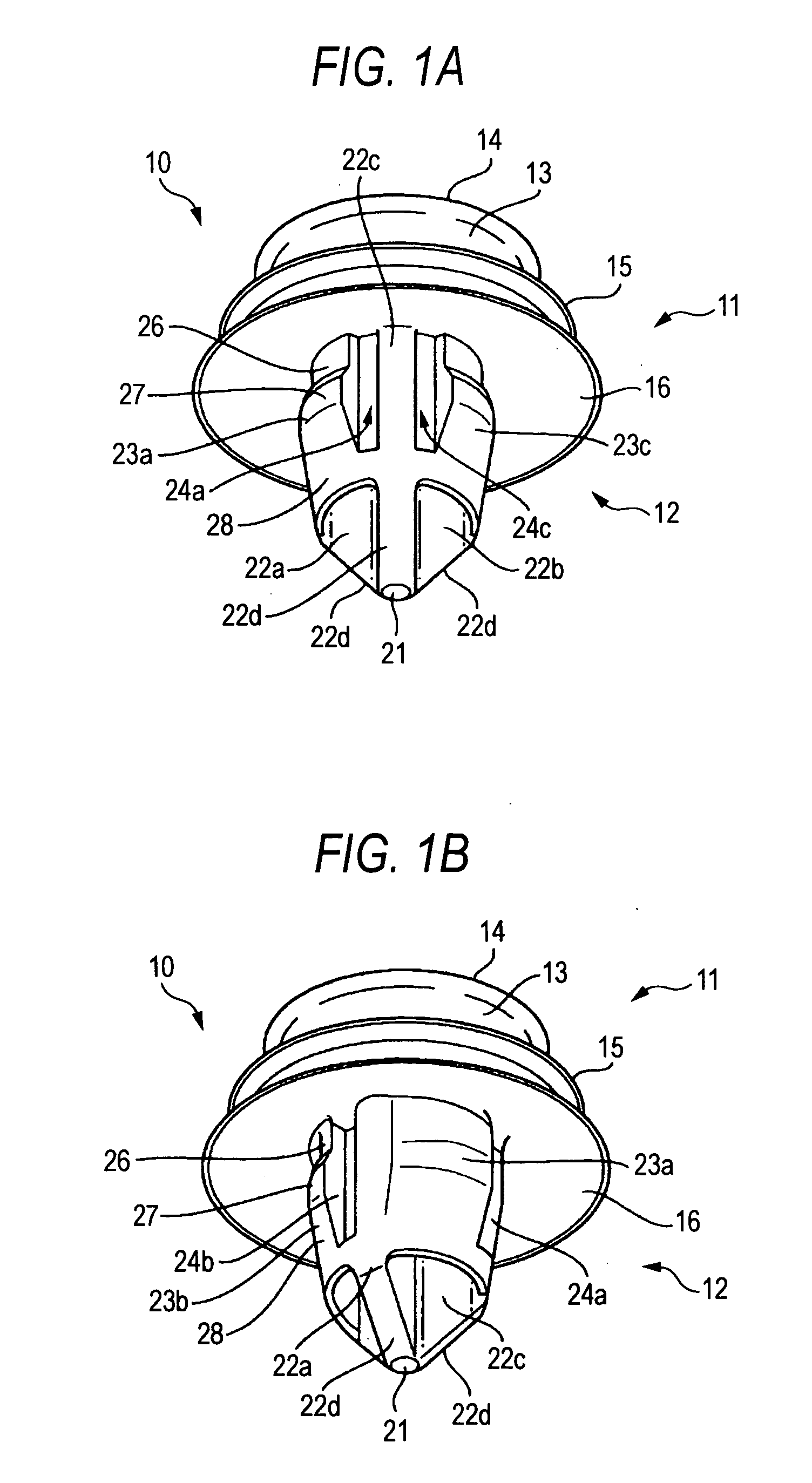
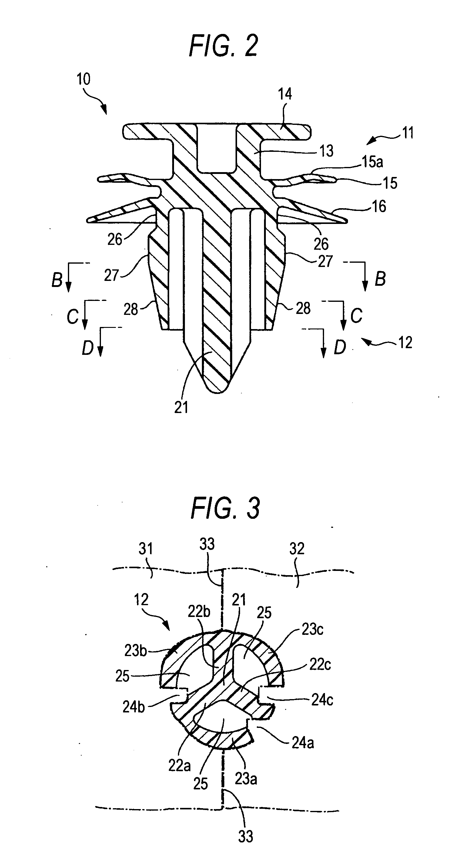
[0029]FIGS. 1A to 7 show one embodiment of a clip according to the invention.

[0030] As shown in FIGS. 1A, 1B and 2, a clip 10 in this embodiment includes a head part 11 and a leg part 12. The head part 11 has a base portion 13 in a bottomed cylindrical shape, a first flange portion 14 which is formed on an outer periphery of this base portion 13 at an upper end thereof, a second flange portion 15 which is formed on the outer periphery of the base portion 13 in the middle part thereof, and a seal portion 16 which is formed on the outer periphery of the base portion 13 in a lower end part thereof.

[0031] The second flange portion 15 has an annular protuberance 15a which is curved upwardly. As shown in FIG. 7, the second flange portion 15 is adapted to be engaged with an engaging groove 18 in a fitting member 17 to clamp a peripheral edge of the engaging groove 18 between the first flange portion 14 and the second flange portion 15, and thus, the clip is fixed to the fitting member 17...


PUM

PropertyMeasurementUnit
outer diameteraaaaaaaaaa
inner diameteraaaaaaaaaa
diameteraaaaaaaaaa

Abstract

A clip has a head part adapted to be contacted with a peripheral edge of a fitting hole in a panel to be fitted, and a leg part adapted to be inserted into the fitting hole thereby to be engaged with the peripheral edge of the fitting hole. The leg part has a post suspended from a center of a lower face of the head part, at least three projections which are radially extended from the post in a diametrical direction and connected to the lower face of the head part at their upper ends, and engaging pieces which are extended from these projections in a circumferential direction to be respectively positioned between the projections. The engaging pieces are connected to the head part at their upper ends, and provided with slits between their circumferentially extended ends and the opposed projections.

Description

BACKGROUND OF THE INVENTION [0001] 1. Field of the Invention [0002] The present invention relates to a clip formed of resin which is utilized for fixing, for example, components to be incorporated inside an automobile or an electric appliance, to a panel part of a vehicle body or a body of the electric appliance, or for fixing another panel to this panel part. [0003] 2. Description of the Related Art [0004] Generally, the clip of this type has a head part adapted to be contacted with a peripheral edge of a fitting hole in a panel to be fitted, and a leg part which is extended from the head part and adapted to be inserted into the fitting hole thereby to be engaged with the peripheral edge of the fitting hole at a back side thereof. [0005] As an example of such clip, Japanese Utility Model Registration No. 2571374 as described below discloses a clip formed of resin and including a head part adapted to be attached to an object for mounting (for example a door trim of an automobile), a...

Claims


Application Information

Patent Timeline
Patent Type & Authority Applications(United States)
IPC IPC(8): F16B5/06F16B19/00F16B21/08
CPCF16B5/065Y10T24/42F16B21/086F16B5/0621F16B19/00F16B21/08B01F23/451B01F25/30B01F25/4334B01F35/71805
Inventor OKADA, SHIGEOKURODA, TAKESHI
Owner PIOLAX CO LTD
Why Eureka
Try Eureka