
Geometric model database for use in ubiquitous computing

a technology of ubiquitous computing and geometries, applied in the field of geometries database, can solve the problems of not having a satisfactory geometries modeling program, and not having a satisfactory geometries databas

Inactive Publication Date: 2005-11-03
MICROSOFT TECH LICENSING LLC
View PDF14 Cites 11 Cited by
  • Summary
  • Abstract
  • Description
  • Claims
  • Application Information

AI Technical Summary

Benefits of technology

[0014] Measurements in the geometric model preferably also reflect the spatial uncertainty associated with the method used to obtain them. One way of introducing an uncertainty estimate into the measurements is to employ a Gaussian uncertainty model where rather than a measurement being a particular value, it is provided to the geometric model program as a mean estimate for each coordinate and a covariance matrix for each that is indicative of the uncertainty of the coordinate mean. One advantage of characterizing the measurements in the foregoing way is that it can be used to enhance certain optional procedures performed within the geometric model program that are designed to test the accuracy and revise the measurements provided to the program. One class of these methods employs the concept of cycle-based constraints. A cycle is a loop formed by connected entities frames. In the environment these loops represent measurements from a first entity frame (which could be any one in the loop) to the next and so on until a measurement connects the next to last entity frame back to the first entity frame. The significance of a cycle is that the measurements around the loop should return precisely to where they started, i.e. a “zero difference”. If they do not then the previously provided uncertainty estimates could be used to adjust the measurements within the loop to obtain the desired zero difference. In this case, measurements are adjusted in proportion to the amount of uncertainty in each one. Specifically, the measurement cycles existing in the geometric model are identified. One of the entities making up each cycle, for which an actual location corresponding the origin of its frame is known, is selected as the first entity of the cycle. The difference between the actual location of the first entity frame's origin and the location of that origin as indicated by following the chain of measurements making up the cycle is then determined. Revised measurements for the identified cycles are computed next by simultaneously adjusting the measurements of all the identified cycles based on their associated uncertainty estimates, so as to make the difference between the actual location of the first entity frame's origin in each of the identified cycles match the location of that origin as indicated by following the chain of measurements making up the cycle.

Problems solved by technology

To date, no satisfactory geometric modeling program exists.
If, however, the specified location falls outside the aforementioned region, then it can be surmised that at least one of the measurements making up the cycle is incorrect.
However, knowing that at least one of them is in error, the geometric model program could be designed to disregard all the measurements that are part of the cycle.
If it is determined that at least one of the measurements making up the cycle is inconsistent, then the measurements are ignored and potentially replaced.
However, the environment being modeled will typically change.
However, when the program is exited the model may be lost.

Method used


Image

  • Geometric model database for use in ubiquitous computing
  • Geometric model database for use in ubiquitous computing
  • Geometric model database for use in ubiquitous computing

Examples


Embodiment Construction

[0038] In the following description of the preferred embodiments of the present invention, reference is made to the accompanying drawings which form a part hereof, and in which is shown by way of illustration specific embodiments in which the invention may be practiced. It is understood that other embodiments may be utilized and structural changes may be made without departing from the scope of the present invention.

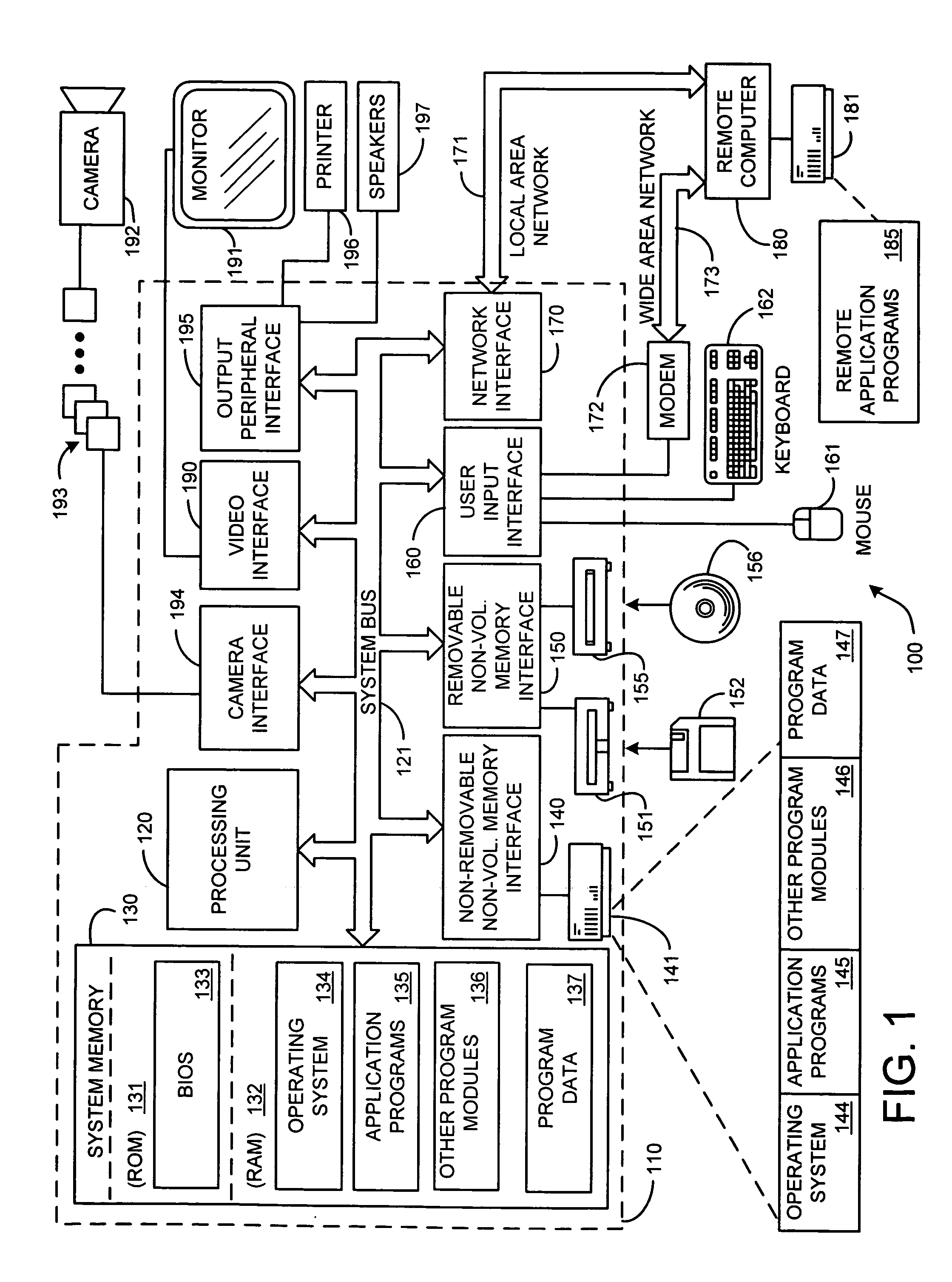
[0039] Before providing a description of the preferred embodiments of the present invention, a brief, general description of a suitable computing environment in which the invention may be implemented will be described. FIG. 1 illustrates an example of a suitable computing system environment 100. The computing system environment 100 is only one example of a suitable computing environment and is not intended to suggest any limitation as to the scope of use or functionality of the invention. Neither should the computing environment 100 be interpreted as having any dependen...


PUM


Abstract

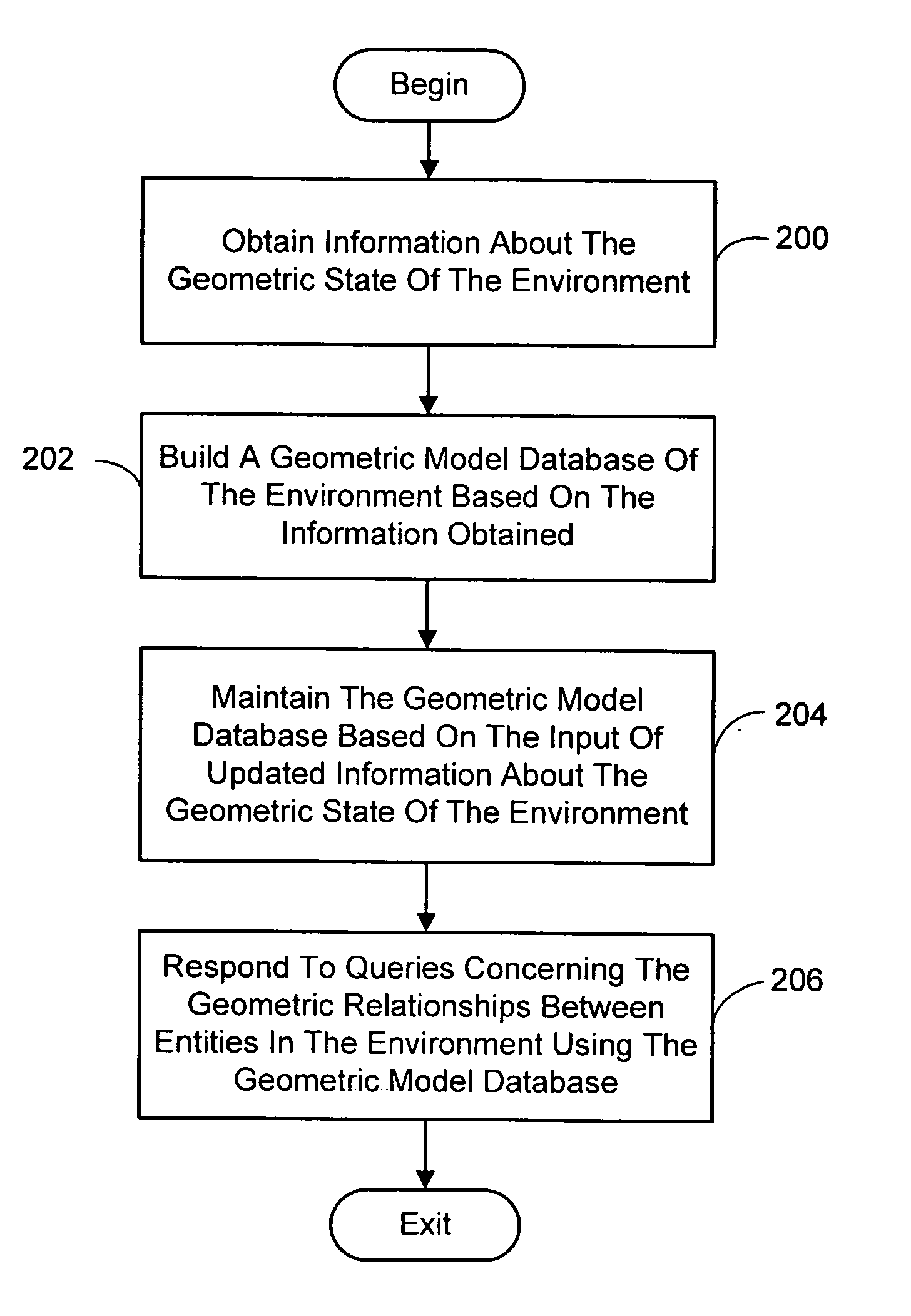
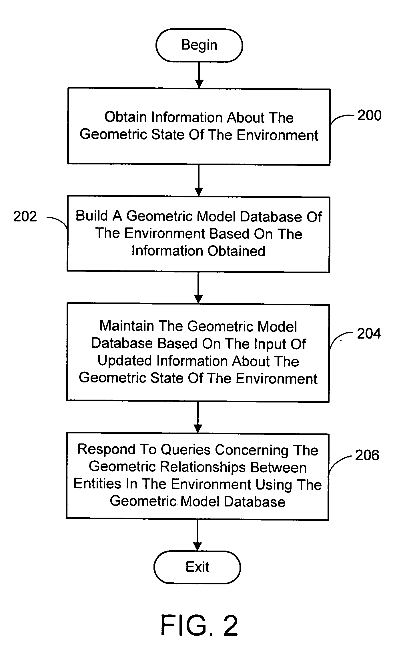
A system and process for providing a geometric model database for use in an ubiquitous computing environment. In general, the geometric model database system and process is capable of accepting information about the geometric state of the environment, building a geometric model of this environment, maintaining and storing the geometric model, and handling queries about the environment's geometric state. The task of building a geometric model begins by establishing a set of entities that are of interest in the environment. An entity represents an object which exists in the physical world. In the geometric model database, an entity is represented by a coordinate frame and an extent. Extents refer to the physical size, or some service region such as a field of view, associated with an entity. The location of an entity in the physical world is defined using “measurements”. In general, a measurement is simply a mathematical description of the geometric relationship between two entities. More precisely, a measurement describes the position and orientation of one entity's coordinate frame, expressed in terms of another entity's coordinate frame. Measurements originating at an entity's frame are expressed in terms of that frame. While various mathematical representations of the geometric relationship between entities could be employed, a preferred one characterizes a measurement as the relative position, and the relative orientation or heading, of two entities along with a covariance matrix which describes the uncertainty in these values.

Description

BACKGROUND [0001] 1. Technical Field [0002] The invention is related to a ubiquitous computing environment, and more particularly to a system and process for providing a geometric model database for use in aggregating information and responding to queries about the environment's geometric state [0003] 2. Background Art [0004] Ubiquitous computing revolves around extending computational activities beyond the current desktop model and into the environment. In future homes and offices, access to computing should be as natural as access to lighting. Users should not be required to go to a special place (i.e., the desktop) to interact with the computer. Rather, the computer should be available to interface with the user anywhere in the home or office (or more generally anywhere in an arbitrarily large environment), through whatever set of devices is available, be they fixed or carried by the user. [0005] It is noted that the term computer is used loosely here in that the user actually wo...

Claims


Application Information

Patent Timeline
Patent Type & Authority Applications(United States)
IPC IPC(8): G06F17/30
CPCG06F17/30A63F2300/69G06F16/00
Inventor BRUMITT, BARRETT L.SHAFER, STEVEN A. N.MEYERS, BRIAN R.
Owner MICROSOFT TECH LICENSING LLC
Learn More