Hydraulic rock splitter

A splitting machine and hydraulic technology, applied in the field of rock hydraulic splitting machine, to achieve the effect of accurate return, good rigidity, and small wear and deformation

Pending Publication Date: 2016-10-12
QINGDAO UNIV OF SCI & TECH
View PDF7 Cites 8 Cited by
  • Summary
  • Abstract
  • Description
  • Claims
  • Application Information

AI Technical Summary

Problems solved by technology

[0005] The technical problem to be solved by the present invention is to design a more reasonable mechanical and hydraulic structure so that the bonding plane of the splitting block and the wedge block will not change when the splitter is working, and reduce equipment damage caused by friction and extrusion. damage; design the force transmission structure to make the force transmission uniform and reduce deformation; use the spring to provide the effect of splitting the return stroke, so that the return position is accurate

Method used


Image

  • Hydraulic rock splitter
  • Hydraulic rock splitter
  • Hydraulic rock splitter

Examples


Embodiment Construction

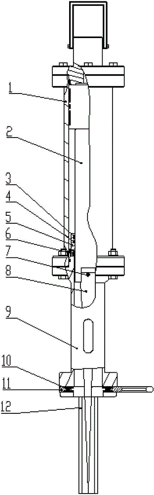
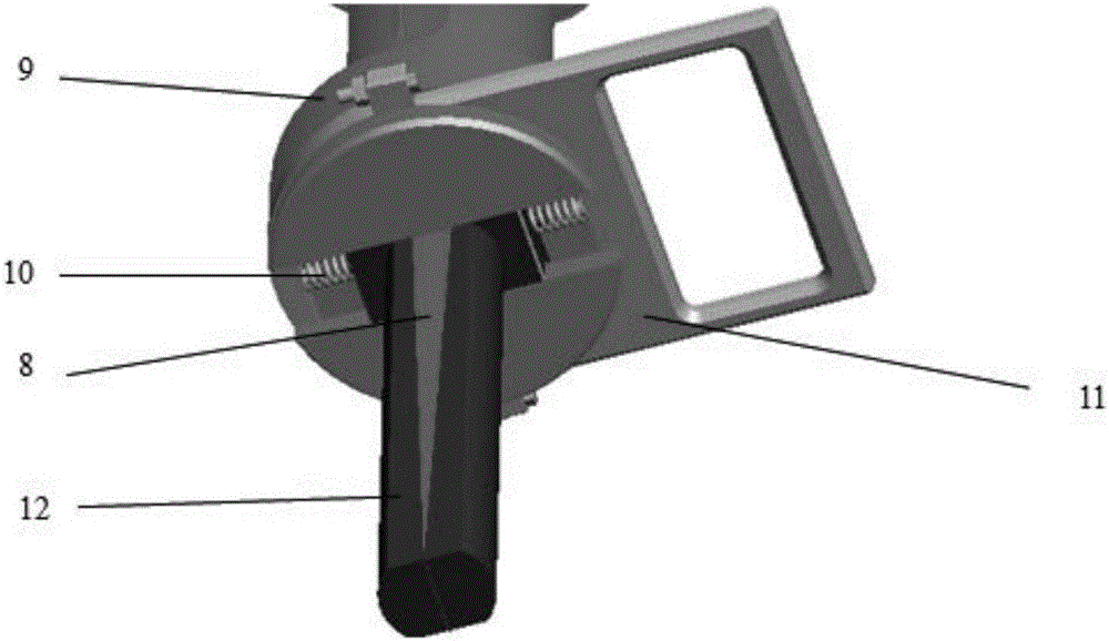
[0012] Such as figure 1 As shown, a hydraulic rock splitting machine includes a hydraulic cylinder 1, a piston rod 2, a sealing block 5, a connecting body 9, a splitting block 12, a wedge 8, a spring 10, and a handle 11. The cylinder 1 and the connecting body 9 are formed, and the two cooperate with each other and are equipped with sealing parts to realize sealing; the force transmission device of the splitter is composed of the rigid connection between the piston rod 2 and the wedge 8; the sealing of the piston rod 2 The guiding device is composed of a sealing block 5, a piston rod guide sleeve 3, an O-ring 4 and an ASW type dust-proof ring 6, which have a sealing and guiding function after being assembled and installed; The spring 10 and the splitting block 12 are assembled and fitted together; the spring 10 is installed on the pin shaft on the handle 11 and the splitting block 12 .

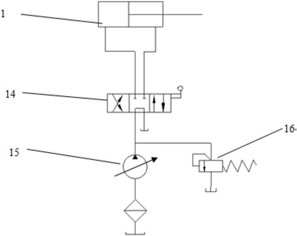
[0013] Such as image 3 As shown, a hydraulic system of a hydraulic rock splitting machin...


PUM


Abstract

The invention discloses a hydraulic rock splitter which comprises a hydraulic cylinder body, a piston rod, a sealing block, a connector, a splitting block, a wedge block, a spring and a handle. The hydraulic cylinder body is composed of a hydraulic cylinder barrel and the connector, and the hydraulic cylinder body is sealed through the connector and a sealing piece. A force transmission device of the splitter is composed of the piston rod and the wedge block, and the piston rod and the wedge block are matched through a cylindrical hole and a cylinder and connected through a fastening screw. A sealing guide device of the piston rod is composed of a piston rod guide sleeve, an O-type sealing ring and an ASW-type dustproof ring which are mounted in an inner hole of the sealing block. A motion part of the splitting block is composed of the connector, the wedge block, the spring and the splitting block. The splitting block is mounted in a T-shaped groove of the connector. The inclined plane of the wedge block is attached to the inclined plane of the splitting block. The hydraulic rock splitter has the beneficial effects of being uniform in part stress, small in equipment abrasion, high in durable degree, convenient to take, high in decomposition efficiency and little in early preparation work, and is suitable for secondary decomposition of exploited granite and large rock, and the cleanliness and yield of stone can be effectively improved.

Description

technical field [0001] The invention relates to a rock hydraulic splitting machine, in particular to a hydraulic splitting machine suitable for secondary decomposition of granite and other rocks and stone mining. Background technique [0002] At present, the main methods of domestic rock decomposition are blasting and breaking hammer decomposition. With the acceleration of national infrastructure, these two methods are greatly restricted and cannot be used under certain conditions. Therefore there is a need for an efficient quarrying method to meet the usage requirements when they cannot be used. [0003] Due to its small size, simple equipment, easy movement, and unlimited use locations; the static pressure is released slowly during work, safe and reliable, no noise, no pollution to the environment, short time to decompose rocks, high efficiency, and rock mining relatively tidy. It can be widely used in stone mining, urban tunnel construction and demolition of buildings....

Claims


Application Information

Patent Timeline
Patent Type & Authority Applications(China)
IPC IPC(8): B28D1/00E21C37/02F15B15/14F15B15/20
CPCE21C37/02F15B15/1461F15B15/20B28D1/00
Inventor 杨化林范工兴张乃华宋正朴赵伟邓芳
Owner QINGDAO UNIV OF SCI & TECH
Why Eureka
Try Eureka