Image reading device and image reading method

a technology of image reading and reading method, which is applied in the field of image reading device and image reading method, can solve the problems of large device, inability to efficiently address the change of print size, and inability to use original fine scan data, and achieve the effect of preventing the effect of positional offs

Inactive Publication Date: 2006-08-10
FUJIFILM HLDG CORP +1
View PDF0 Cites 7 Cited by
  • Summary
  • Abstract
  • Description
  • Claims
  • Application Information

AI Technical Summary

Benefits of technology

[0024] In this way, the image reading conditions are changed, and the actual reading can be carried out again. Thus, even cases in which trimming of the image or changing of the print size is instructed can be addressed, and the image can be read more properly.
[0025] Moreover, preliminary reading and actual reading are carried out in continuation. However, the photographic film is not conveyed immediately thereafter, and rather, the photographic film is conveyed after the inspection processing. Therefore, even in cases in which actual reading is required again due to the results of the inspection processing, there is no need to convey the photographic film rearward and rewind it. In the case of a photographic film in which no perforations are formed, the photographic film is not necessarily returned accurately to the reading position when conveyed reversely. However, by invariably conveying the photographic film after the inspection processing as in the present invention, it is possible to prevent the effects of positional offset which arise due to reverse conveying.

Problems solved by technology

Therefore, the original fine scan data cannot be used, and fine scanning must be executed again.
Cases in which it is desired to trim the image or change the print size cannot be addressed efficiently.
Therefore, if an attempt is made to use information of two frames as in the case of a 135-size photographic film, the device becomes large.

Method used


Image

  • Image reading device and image reading method
  • Image reading device and image reading method
  • Image reading device and image reading method

Examples


Embodiment Construction

[0043] An embodiment of the present invention will be described hereinafter with reference to the drawings.

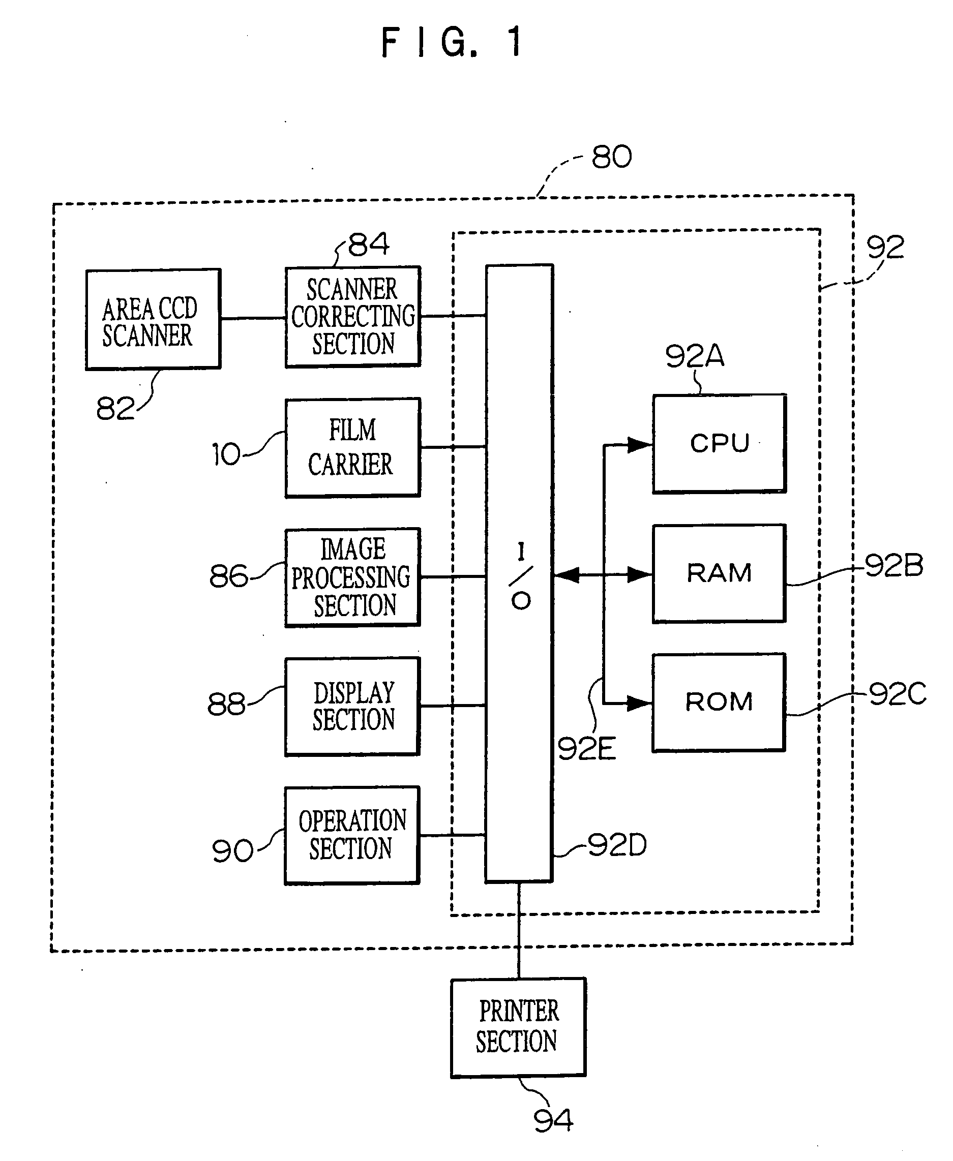
[0044] A block diagram of the schematic structure of an image reading device 80 relating to the present embodiment is shown in FIG. 1.

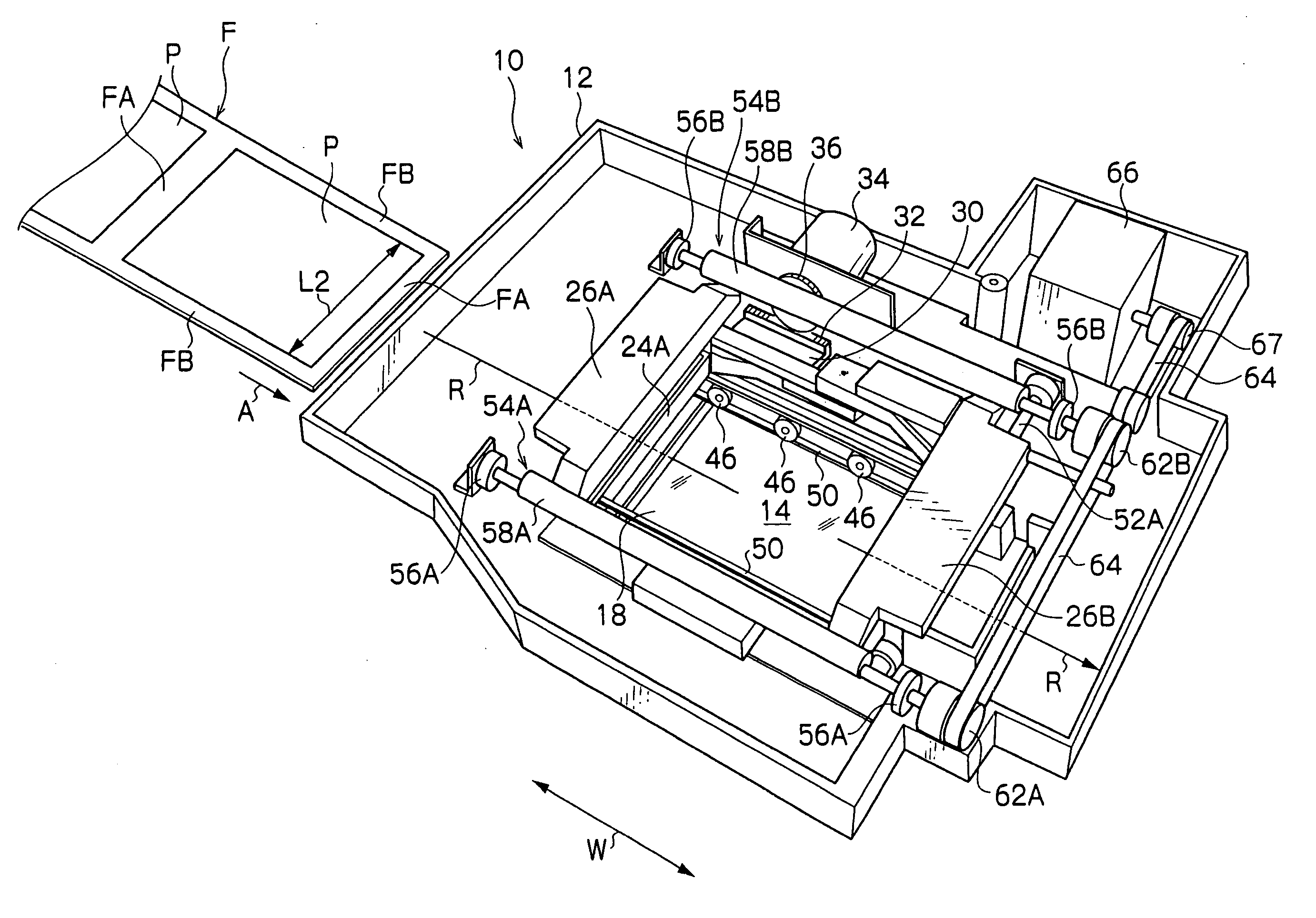
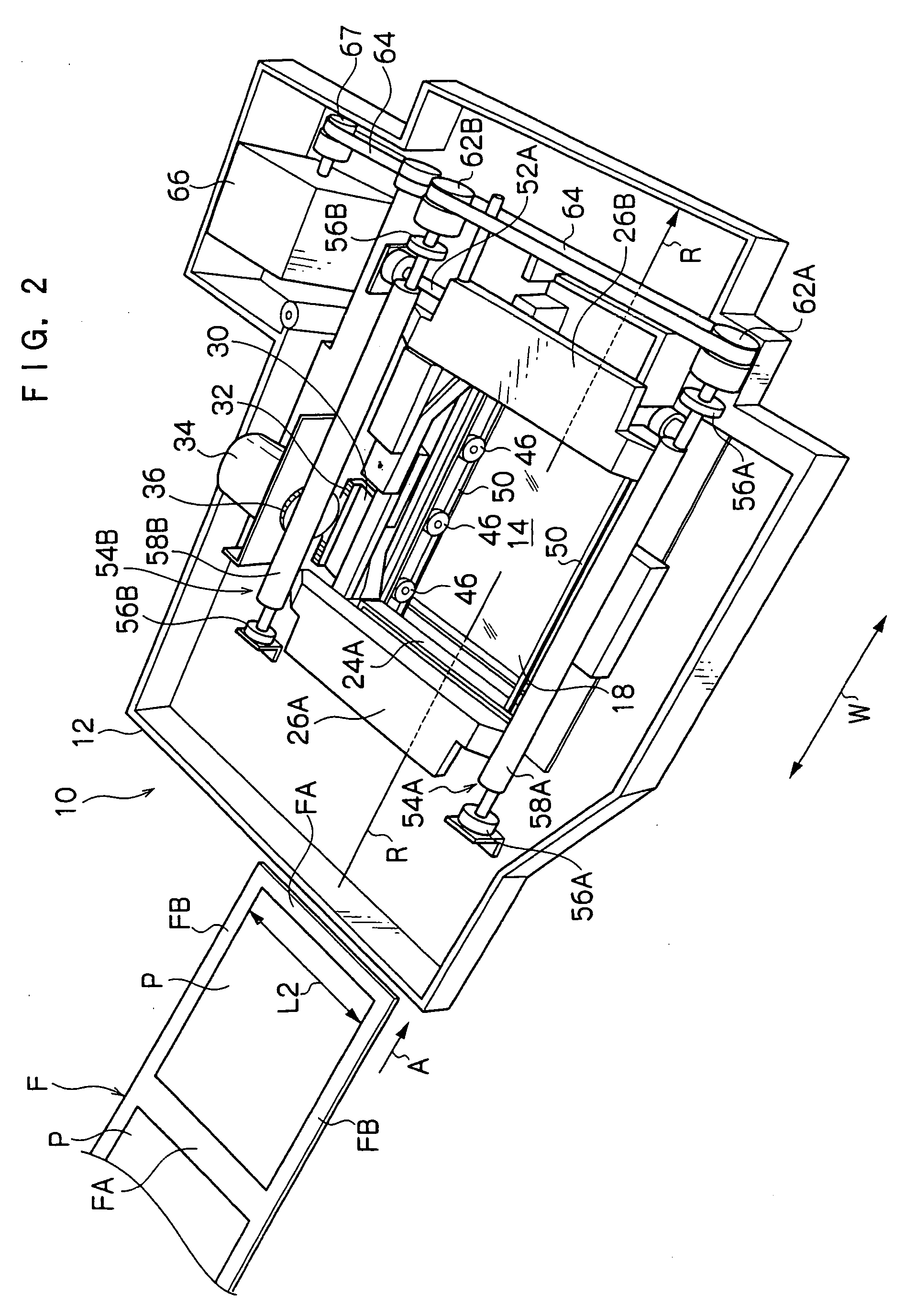
[0045] The image reading device 80 is structured so as to include an area CCD scanner 82, a scanner correcting section 84, a film carrier 10, an image processing section 86, a display section 88, an operation section 90, and a microprocessor 92.

[0046] The area CCD scanner 82 is for reading the respective image frames recorded on a photographic film. In the present embodiment, as an example, a film image of a photographic film in which no perforations are formed, e.g., a so-called brownie size (120 size, 220 size) photographic film, is used as the object of reading.

[0047] The area CCD scanner 82 is structured so as to include a light source, an optical lens, an area CCD serving as an image pickup element, an A / D converter, and the like, none o...


PUM


Abstract

In an image reading system, a photographic film is conveyed, an image frame is conveyed to a reading position, pre-scanned and fine scanned. An image obtained by pre-scanning is displayed on a display section. The film is conveyed after the inspection processing ends. Further, by using data output from six image surface detecting sensors disposed along a transverse direction of the film, inter-frame region candidates (edge candidates) are detected within an inspection range per frame. A region surmised to be between frames is detected from film light amounts input from the sensors. Edge slopes, the edges' density differences, are computed as evaluation values for detecting an edge to be used as a reference from among the candidates, and are compared. An edge having a largest density difference is extracted. With the extracted edge as a reference, an image frame position is determined while considering an image frame size.

Description

CROSS-REFERENCE TO RELATED APPLICATIONS [0001] This application claims priority under 35 USC 119 from Japanese Patent Applications Nos. 2005-028813 and 2005-029240, the disclosures of which are incorporated by reference herein. BACKGROUND OF THE INVENTION [0002] 1. Technical Field [0003] The present invention relates to an image reading method, and in particular, relates to an image reading method which reads an image frame recorded on a photographic film. [0004] The present invention relates to an image reading device and an image reading method, and in particular, relates to an image reading method which reads an image frame recorded on a photographic film, and to an image reading device and an image reading method which read an image recorded on a recording medium such as a photographic film or the like. [0005] 2. Description of the Related Art [0006] Conventionally, there have been known image outputting devices which read, by a scanner equipped with a reading sensor such as a C...

Claims


Application Information

Patent Timeline
Patent Type & Authority Applications(United States)
IPC IPC(8): H04N1/46
CPCG03B1/32G03B1/40G03B1/48G03B1/60H04N1/04H04N2201/0408H04N2201/0416
Inventor KATO, KENICHIKURONO, HIROSHI
Owner FUJIFILM HLDG CORP
Why Eureka
Try Eureka