
Coding of audio signals

Inactive Publication Date: 2005-11-03
NOKIA CORP
View PDF14 Cites 102 Cited by
  • Summary
  • Abstract
  • Description
  • Claims
  • Application Information

AI Technical Summary

Benefits of technology

[0015] One aim of the present invention is to provide an improved method for encoding audio signals in an encoder for reducing annoying audible effects when switching between the modes having different bandwidths. The invention is based on the idea that when the change happens from narrowband (AMR-WB mode) to wideband mode (AMR-WB+) the high band extension is not turned on immediately but the amplitude is only gradually increased to final volume to avoid too rapid change. Similarly, when switching from wideband mode to narrowband mode, the high band extension contribution is not turned off immediately but it is scaled down gradually to avoid disturbing effects.
[0016] According to the invention, such gradual introduction of the high band extension signal is realized at the parameter level by multiplying the excitation gains used for the high band synthesis with a scaling factor that is increased in small steps from zero to one within a selected time window. In e.g. AMR-WB+ codec a window length of 320 ms (4 AMR-WB+ frames of 80 ms) can be expected to provide slow enough ramp-up of the high band audio contribution. In the same way as in ramp-up of the high band audio contribution, also the gradual termination of the high band signal can be realised at parameter level, in this case by multiplying the excitation gains used for high band synthesis with a scaling factor that is decreased in small steps from one to zero during selected period of time. However, in this case we do not have updated parameters for the high band extension available once the actual switching to a core band only mode has happened. However, the high band synthesis can be performed by using the high band extension parameters received for the last frame before switching to the core only mode and the excitation signal derived from the frames received in the core only mode. A slightly modified version of this method would be to modify the LPC parameters used for the high band synthesis after the switching in such a way that the frequency response of the LPC filter is gradually forced towards more flat spectrum. This can be realised e.g. by computing a weighted average of the actually received LPC filter and a LPC filter providing a flat spectrum in ISP domain. This approach might provide improved audio quality in cases where the last frame with high band extension parameters happened to include clear spectral peak(s).
[0017] The method according to the present invention provides a similar effect as direct scaling in time domain, but performing the scaling at parameter level is computationally a more efficient solution.
[0025] Compared to the prior-art approach presented above, the invention provides a solution for reducing the possible audible effects due to the switching between different bandwidth modes. Hence, the audio signal quality can be improved. The present invention provides similar functionality as direct scaling in the time domain, but performing the scaling at the parameter level is computationally more efficient solution.

Problems solved by technology

However, in this case we do not have updated parameters for the high band extension available once the actual switching to a core band only mode has happened.

Method used


Image

  • Coding of audio signals
  • Coding of audio signals
  • Coding of audio signals

Examples


Embodiment Construction

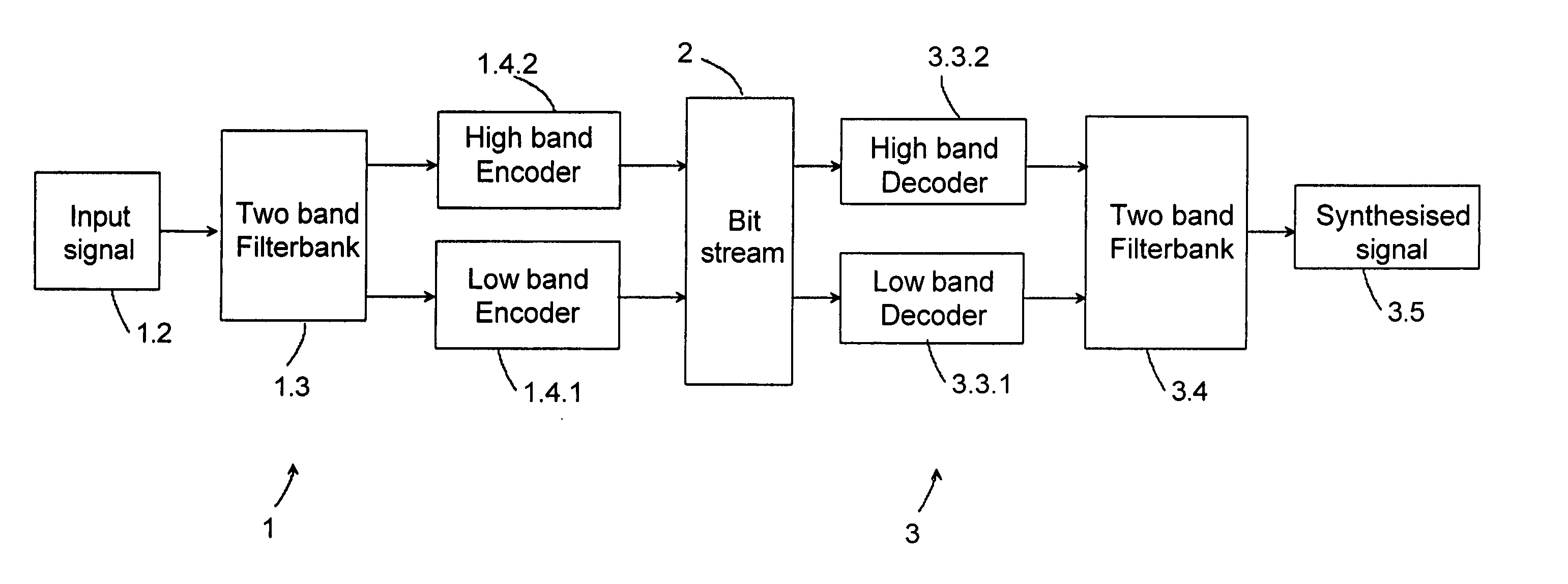
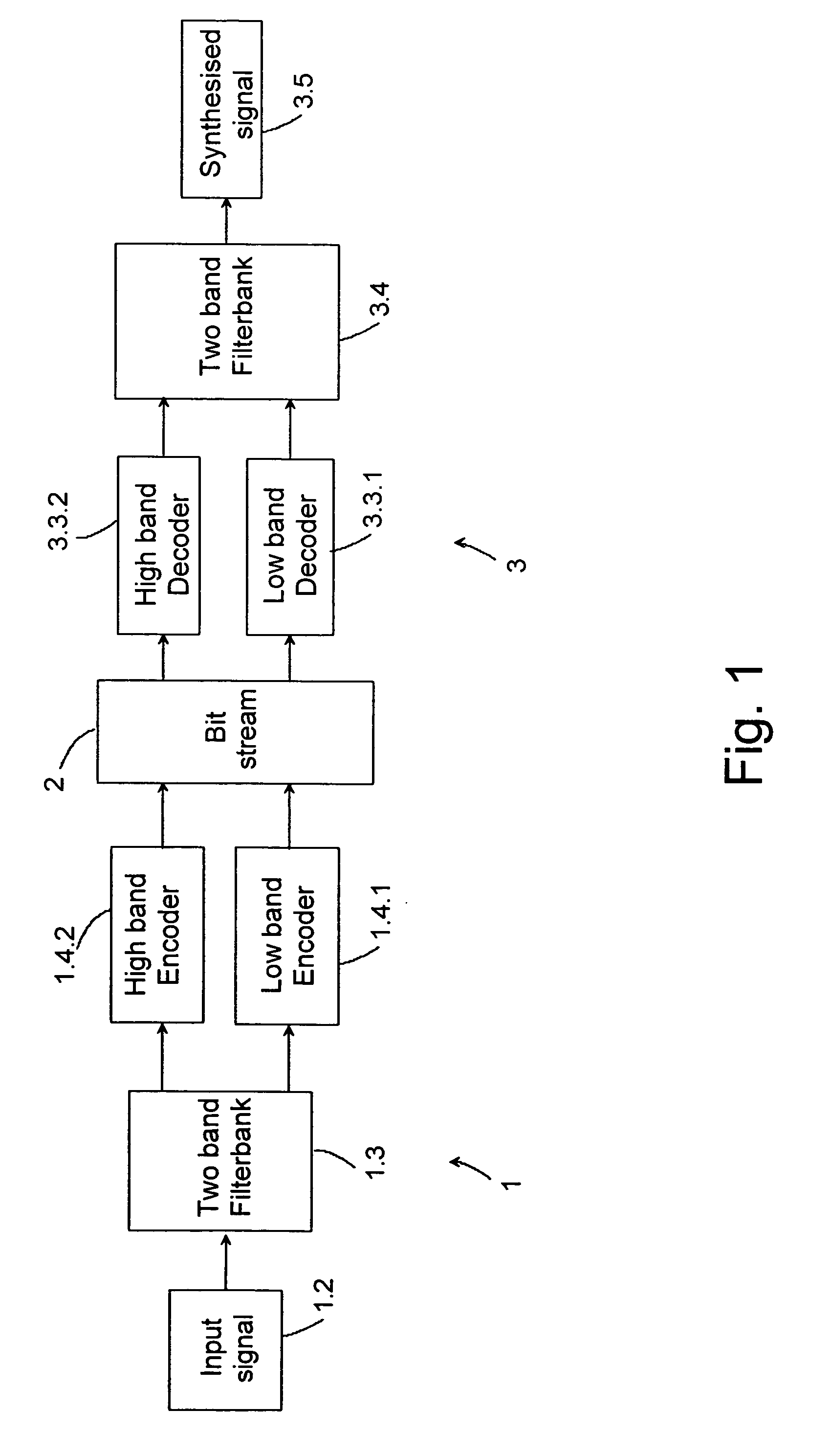
[0036]FIG. 1 presents the split band encoding and decoding concept according to an example embodiment of the present invention using two band filter banks and separate encoding and decoding blocks for each audio band. An input signal from a signal source 1.2 is first processed through an analysis filter 1.3 in which the audio band is divided into at least two audio bands, i.e. into a lower frequency audio band and a higher frequency audio band, and critically down sampled. The lower frequency audio band is then encoded in a first encoding block 1.4.1 and the higher frequency audio band is encoded in a second encoding block 1.4.2, respectively. The audio bands are encoded substantially independently on each other. The multiplexed bit stream is transmitted from the transmitting device 1 through a communication channel 2 to a receiving device 3 in which the low and high bands are decoded independently in a first decoding block 3.3.1 and in a second decoding block 3.3.2, respectively. T...


PUM


Abstract

An encoder comprises an input for inputting frames of an audio signal in a frequency band, an analysis filter dividing the frequency band into lower and higher frequency bands, a first encoding block for encoding the audio signals of the lower frequency band, a second encoding block for encoding the audio signals of the higher frequency band, and a mode selector for selecting an operating mode for the encoder among at least a first mode where signals only on the lower frequency band are encoded, and a second mode where signals on both the lower and higher frequency band are encoded. The encoder has a scaler to gradually change the encoding properties of the second encoding block in connection with a change in the operating mode of the encoder. The invention also relates to a device, a decoder, a method, a module, a computer program product, and a signal.

Description

CROSS-REFERENCE TO RELATED APPLICATIONS [0001] This application claims priority under 35 USC §119 to Finnish Patent Application No. 20045135 filed on Apr. 15, 2004. FIELD OF THE INVENTION [0002] The present invention relates to an encoder comprising an input for inputting frames of an audio signal in a frequency band, an analysis filter for dividing the frequency band into at least a lower frequency band and a higher frequency band, a first encoding block for encoding the audio signals of the lower frequency band, a second encoding block for encoding the audio signals of the higher frequency band, and a mode selector for selecting an operating mode for the encoder among at least a first mode and a second mode, in which first mode signals only on the lower frequency band are encoded, and in which second mode signals on both the lower and higher frequency band are encoded. The invention also relates to a device comprising an encoder comprising an input for inputting frames of an audio...

Claims


Application Information

Patent Timeline
IPC IPC(8): G10LG10L19/24G10L25/18
CPCG10L25/18G10L19/24G10L19/02G10L19/06G10L19/08
Inventor OJALA, PASIMAKINEN, JARILAKANIEMI, ARI
Owner NOKIA CORP
Learn More