
Mobile portal for radio frequency identification of objects

a mobile portal and radio frequency identification technology, applied in the field of application of radio frequency identification (rfid) technology, can solve the problems of inconvenient deployment of a sufficient number of rfid reader portals in a warehouse to locate precisely where a tagged palette is all times, and the present day rfid system is not cost effective for locating assets more precisely, etc., and achieves the same cost disadvantages of fixed rfid reader portal system, and r

Inactive Publication Date: 2005-11-03
SYMBOL TECH INC
View PDF8 Cites 96 Cited by
  • Summary
  • Abstract
  • Description
  • Claims
  • Application Information

AI Technical Summary

Benefits of technology

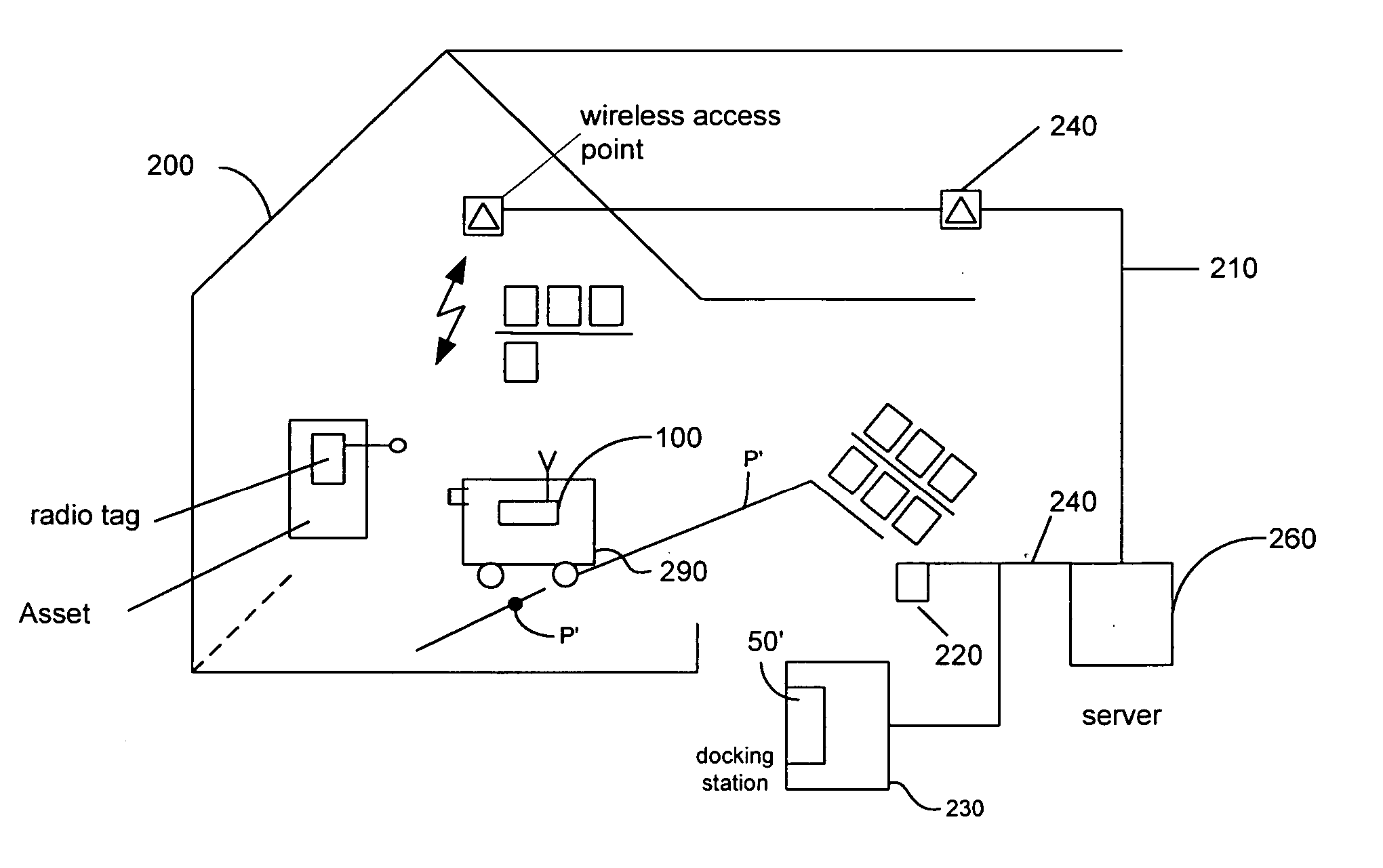
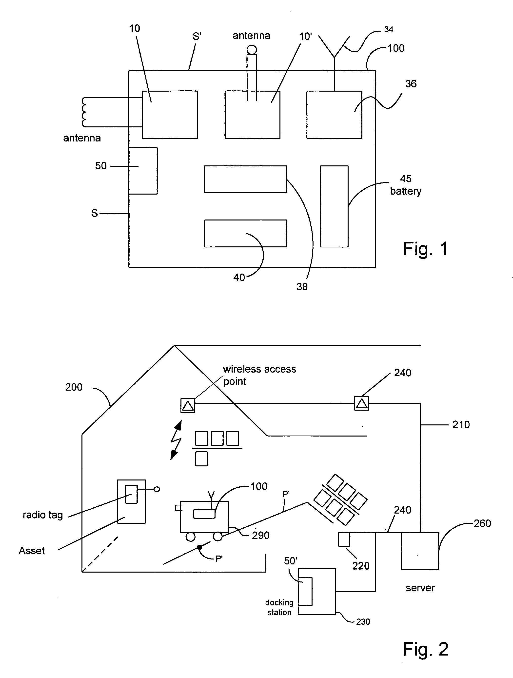
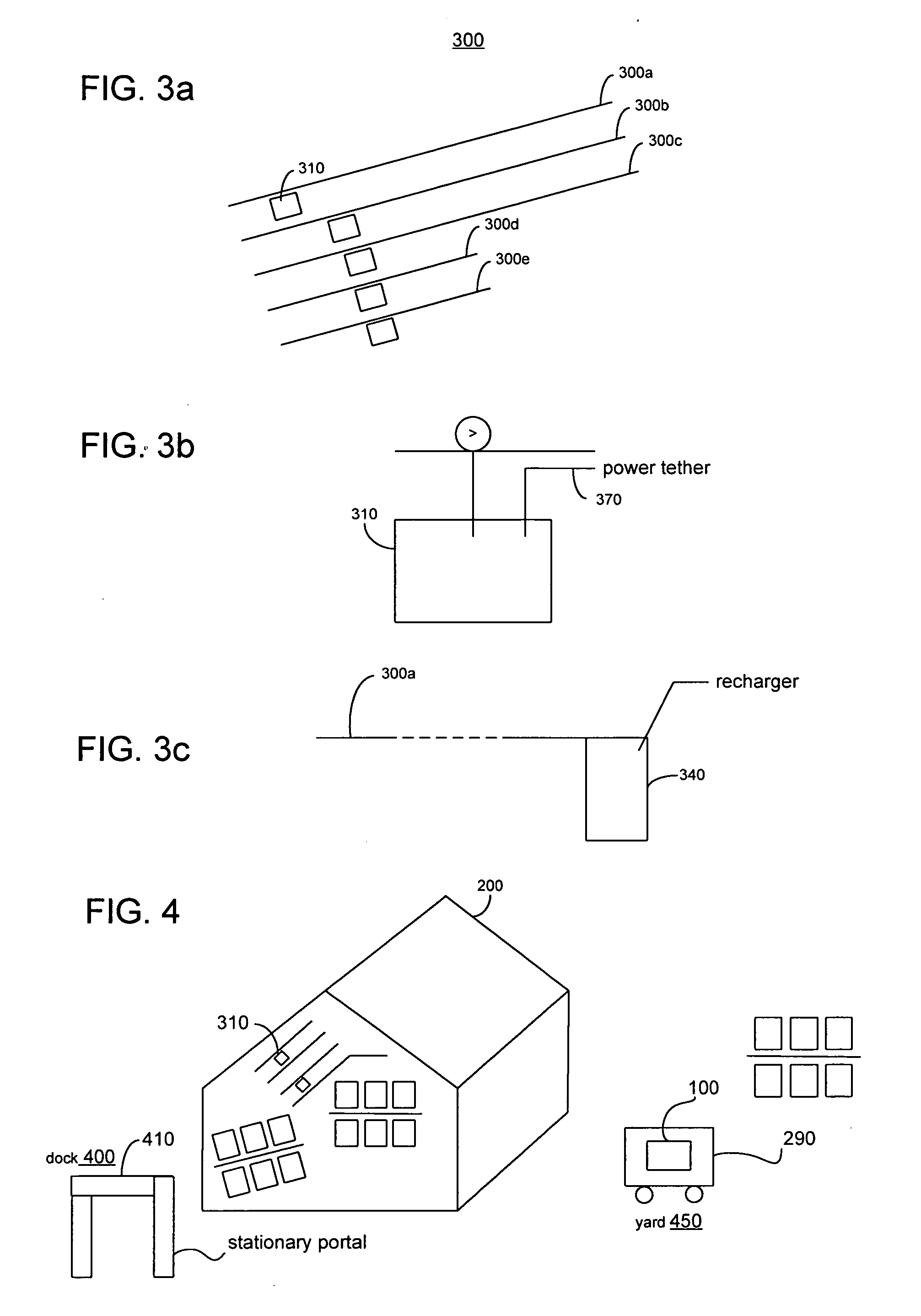
[0011] In an embodiment of the invention, a system for locating RFID-tagged assets includes at least one of mobile RFID portal for reading RFID tags. The mobile RFID portal includes an antenna / transceiver reader unit for reading RFID tags using for example, low power RF signals. The reader unit may have a short range. The mobile RFID portal is moved through the area of interest (e.g., a warehouse) along a select path to read RFID tags on assets present in the vicinity of the path. The read RFID tag information is co-related or associated with the position of the mobile RFID portal along the path to precisely locate the assets in the vicinity of the path. Conventional data processing arrangements may be used to analyze the RFID tag information and the data on the mobile RFID portal positions. The read RFID tag information may be time stamped for correlating the locations of the assets with the position of the mobile RFID portal. Time stamping of the RFID tag information also may be advantageously used for time-tracking or analysis of the movement of assets.

Problems solved by technology

However, present day RFID systems are not cost effective for locating assets more precisely, for example, in large warehouse or buildings, or for locating high-value assets to within a few feet.
The space requirements and the cost of deploying a sufficient number of RFID reader portals in a warehouse to locate precisely where a tagged palette is all times can be prohibitive.
However, RTLS also has the same cost disadvantages of fixed RFID reader portal systems at least because it involves the use of expensive battery-powered active RFID tags.

Method used


Image

  • Mobile portal for radio frequency identification of objects
  • Mobile portal for radio frequency identification of objects
  • Mobile portal for radio frequency identification of objects

Examples


Embodiment Construction

[0022] In accordance with the invention, a configuration of mobile RFID portals is provided for use in the radio frequency identification and location of assets. The configuration of mobile RFID portals may be deployed in an area of interest to determine, on a continuous or periodic basis, the locations of RFID-tagged assets within the area.

[0023] For convenience in the description herein, a warehouse building (building 200FIG. 2) is used as the exemplary area of interest. It will, however, be understood that the area of interest may be any area in which of assets are stored, moved or used (e.g. a transportation yard, retail store, a manufacturing plant, or other buildings or spaces). Warehouse building 200 may be serviced in a conventional manner by wireless and / or wired networks for data communications that, for example, are commonly used in present day business operations. FIG. 2 shows, for example, wireless access points 240 of a wireless data communications network 210, which ...


PUM


Abstract

A system utilizes radio frequency identification (RFID) technology to determine the precise location of assets within a large area or building. RFID tags are attached to the assets. A mobile RFID portal, which includes an RFID tag reader, is moved along a select path through the large area or building to read information from RFID tags present in the vicinity of the path. The mobile RFID portal may be moved along the floor or on an overhead rail. The RFID tag information is analyzed along with data on the positions of the mobile RFID portal along the path and / or data on the times-of-read to determine the location of assets associated with the read RFID tags.

Description

BACKGROUND OF THE INVENTION [0001] The present invention relates to applications of radio frequency identification (RFID) technology that is used for identifying items or assets. [0002] RFID technology exploits electromagnetic or electrostatic coupling in the radio frequency (RF) portion of the electromagnetic spectrum to uniquely identify and locate an item or asset. A conventional RFID system includes three primary components: an antenna and transceiver (often combined into one reader unit), and electronic devices called transponders or tags (the RFID tags) that are attached to the items or assets. The reader unit emits radio waves, and when an RFID tag is within the range of the reader unit, the tag responds and starts sending data. [0003] RFID tags come in a wide variety of size, shapes and forms but have common attributes; each includes low-energy broadcast circuitry, programmable data storage and operating circuitry. Tags come with and without batteries, they can be read only ...

Claims


Application Information

Patent Timeline
Patent Type & Authority Applications(United States)
IPC IPC(8): G06K7/00G06K17/00
CPCG06K7/0008G06K7/10079G06Q10/087G06K2017/0051G06K2017/0045
Inventor VESUNA, SAROSH
Owner SYMBOL TECH INC
Learn More