Football throwing machine

a throwing machine and ball technology, applied in the field of ball throwing machines, can solve the problems of large equipment, large weight, and significant effort to operate, and achieve the effect of low power consumption, convenient transportation, and low cos

Inactive Publication Date: 2011-03-15
FENLEY EDWARD ANTHONY
View PDF19 Cites 15 Cited by
  • Summary
  • Abstract
  • Description
  • Claims
  • Application Information

AI Technical Summary

Benefits of technology

[0013]An effective training device for football catching practice will have many desirable characteristics. It must replicate a manually thrown football as closely as possible, while providing consistency and accuracy so a specific catch can be repeated as many times as necessary. The football should have a repeatable helical spin as it travels so as to steady the ball in flight. The equipment should have a mechanism for delaying the release of the football so the user can position to catch the football when it arrives at its destination. In this way the trainee can duplicate the run patterns used in a football game, repeating each run and receipt in exactly the same fashion. Additional desirable characteristics of this training equipment include portability and low power consumption. Equipment should be mobile enough to be easily transported to a practice field and should operate on inexpensive, portable power while in use. It should also be lightweight and simple enough to setup and operate so that users of less than adult size and strength can make use of the equipment.
[0014]This invention addresses these requirements by matching efficient spring power with mechanical leverage to allow the user to provide the propulsion energy required for throwing the football. An efficient triggering mechanism allows the equipment timing and triggering actions to be completed using only battery power. The helical spin is directly and efficiently achieved by passing the football through a set of freely spinning wheels that are angled to apply the rotational force required to achieve the spin on the football. The result is portable, inexpensive, easy to use equipment for accurately and repeatedly throwing footballs.

Problems solved by technology

While these techniques may produce a throw, the equipment is large, bulky and can require significant effort to operate.
This method is unlikely to produce the accuracy and consistency required for practical use.
The wheels are slightly misaligned with one another, thus creating the spin required for a steady flight.
The disadvantages of this design include the large size and weight, the high cost of components and the requirement for high voltage alternating current power, which is frequently unavailable on a practice field.
Also, the equipment did not have a method of throwing a ball to oneself, as an operator is required to aim and feed the ball into the equipment.
This design includes a timer for one person operation; however this design has the disadvantage of requiring a special football with a hole through the center.
Adjustments to the throw distance, pulling back the elastic bands, and loading the football, all appear to be somewhat cumbersome.
Disadvantages of this design include the complexity of the assembly, likely high cost, and likelihood of being very cumbersome in practical use.
Disadvantages to this design are the size, weight and complexity of the equipment as well as the availability and expense of delivering high voltage power or compressed air to the place of use.
This device is battery powered and portable, but has the disadvantage of requiring a custom, non regulation football and can best be described as a toy for children.
It has a delay mechanism, however the timing varies only to the degree that the equipment requires more time to generate higher pressures for longer throws.

Method used


Image

  • Football throwing machine
  • Football throwing machine
  • Football throwing machine

Examples


Embodiment Construction

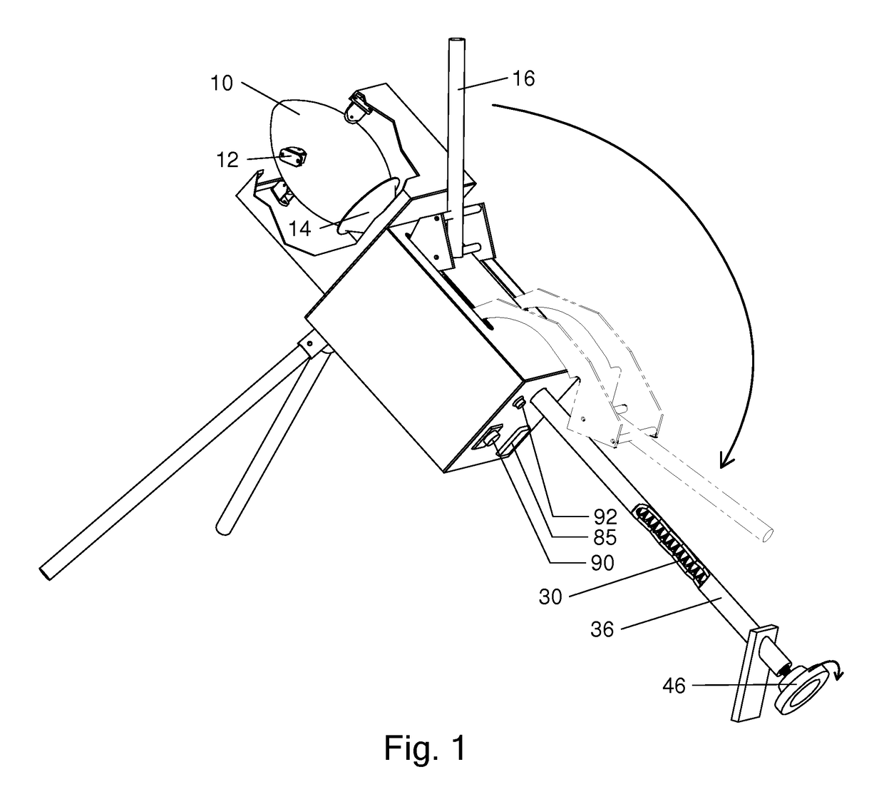
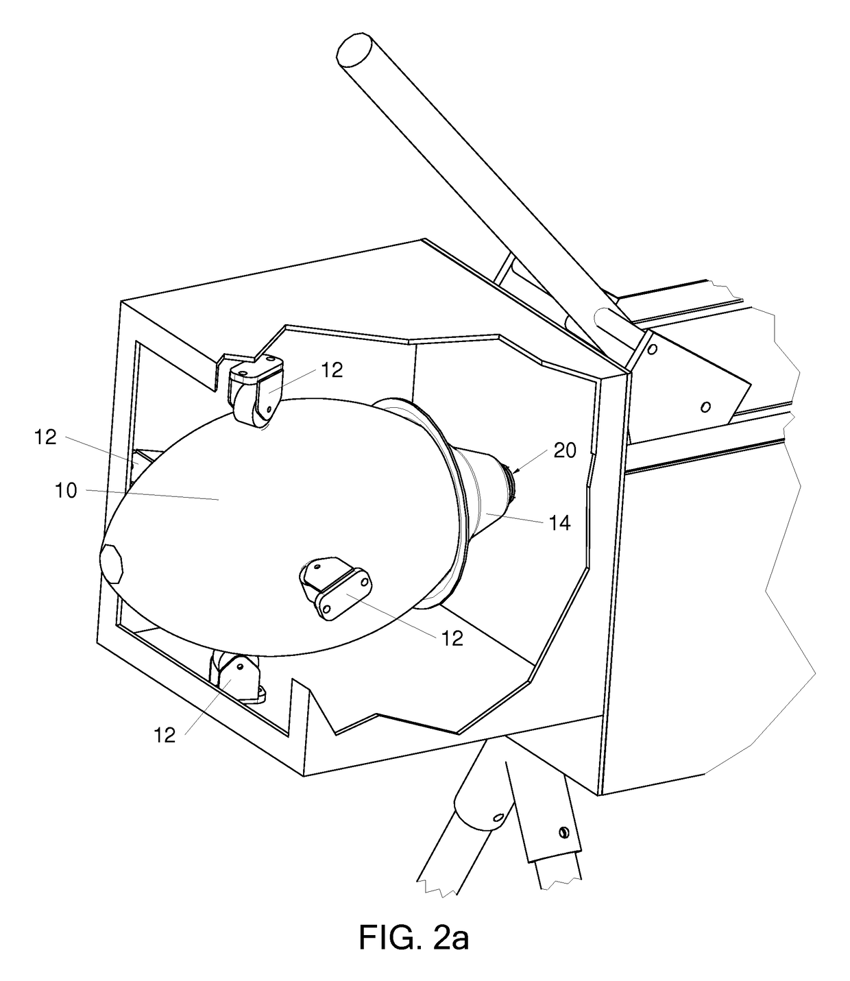
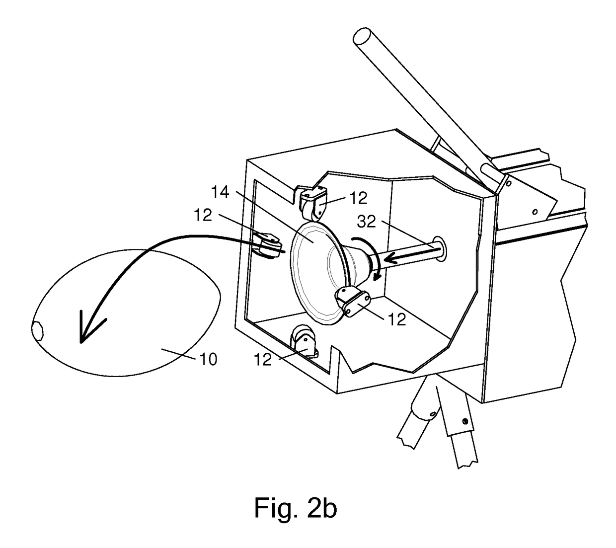
[0028]FIG. 1 illustrates one embodiment of this invention showing the basic operation. A spring 30 is enclosed in a tube 36 and positioned so that a football 10 will align along the same axis. The spring 30 is compressed by moving a handle 16 as shown to compress the spring. The handle 16 is returned to its original position prior to launching the football 10. A detailed description of this action is described in FIG. 4. The spring 30 is held in its compressed state by a latching mechanism, one embodiment of which is described in FIGS. 5a-5c. The football 10 can then be loaded in the front end of the equipment so it rests against a rotating cup 14. The football 10 is held in place radially by several (at least three) free-spinning spin wheels 12 that both hold the football 10 and provide the mechanism for spinning the football 10 upon release. This is described in detail in FIGS. 2a and 2b. The launch cycle begins by the operator setting a timer 90 for the desired delay and pressing...


PUM


Abstract

One embodiment of a football throwing machine using an axially aligned compression spring for propulsion and a latching mechanism for retaining the spring in its compressed state. A spiral shaped actuator mechanism is used to compress the spring with consistent torque throughout the compression stroke. The spring is released from its compressed state using an efficient triggering mechanism. A timing mechanism allows a delay so the user can position for the catch. The football is held by axially misaligned wheels on one end and a rotating cup on the other. As the spring pushes the ball between the wheels while being ejected from the apparatus, the wheel misalignment causes the helical spinning effect on the football while the cup holding the other end of the football spins freely.

Description

CROSS-REFERENCE TO RELATED APPLICATIONS[0001]NoneFEDERALLY SPONSORED RESEARCH[0002]Not ApplicableSEQUENCY LISTING OR PROGRAM[0003]Not ApplicableBACKGROUND[0004]1. Field of the Invention[0005]This invention relates to a machine designed to repeatedly and accurately throw a football shaped object for catching practice, without the required assistance of a second person.[0006]2. Prior Art[0007]There have been numerous attempts to produce equipment capable of achieving repeatable, accurate football throws for use in catching practice. Designs by Dixon (U.S. Pat. Nos. 3,926,170, 3,951,125) and Meyer (U.S. Pat. No. 3,977,386) employed vertical and horizontal cantilever arms to simulate the arm motion of a quarterback. Centrifugal force and friction imparted the spinning effect required for stability during the ball flight. While these techniques may produce a throw, the equipment is large, bulky and can require significant effort to operate. Additionally, the ball spin that is required is...

Claims


Application Information

Patent Timeline
Patent Type & Authority Patents(United States)
IPC IPC(8): F41B7/00
CPCA63B69/407A63B2069/401A63B2069/402
Inventor FENLEY, EDWARD ANTHONY
Owner FENLEY EDWARD ANTHONY
Why Eureka
Try Eureka