Camera system and power supply for optical recording devices

a power supply and optical recording technology, applied in the field of ergonomic camera system and power supply for optical recording devices, can solve the problems of physical small batteries generally provided with these cameras, video cameras commonly require 50% of the power that earlier cameras 600% larger would consume, and the weight distribution of optical recording devices is not reduced in similar proportions. , to achieve the effect of improving the ergonomics of an electrical device and improving the weight distribution of an optical recording devi

Inactive Publication Date: 2007-03-15
ANTONBAUER
View PDF66 Cites 15 Cited by
  • Summary
  • Abstract
  • Description
  • Claims
  • Application Information

AI Technical Summary

Benefits of technology

[0025] It is yet another object of the present invention to provide a battery assembly for an optical recording device that improves the weight distribution of an optical recording device.
[0026] It is yet another object of the present invention to provide a battery assembly that improves the ergonomics of an electrical device.

Problems solved by technology

However, the power requirements of these handheld video cameras have not been reduced in similar proportions to their reduction in size and weight.
Indeed, today's video cameras commonly require 50% of the power that earlier cameras 600% larger would consume.
The batteries generally provided with these cameras are physically small, limited in their ability to power the cameras for extended periods of time and are generally considered unreliable for long service life or professional use.
The batteries included with known handheld video cameras often define a footprint (length and width) for their mounting means that is itself small in area, and therefore only allows for extending the battery outwardly from the camera body, resulting in an awkward and mostly unusable dimension.
Also, the footprint does not allow for the increase in the size of the cells used in the battery.
Therefore, improving the performance or quality of the battery is virtually impossible.
The reduction in size and weight of known handheld video cameras also creates a problem in the physics behind the ability of a pan and tilt head to properly control the movement of the camera.
Thus, the reduction in size and weight of handheld cameras has caused a problem for both the power source and the stabilizing devices typically used, especially by professionals, to operate the camera to generate quality video productions.
These devices typically add to the operators weight burden both in camera operation and in the weight of gear necessary to carry to a location.
These devices are often awkward and mitigate the size and weight benefits, and operating convenience, that small cameras were intended to offer.
Still further, the reduction in the size of the camera body has left little room to add or attach accessory devices.
While still photography cameras are themselves oftentimes provided with a threaded bore for optional mounting upon a tripod or the like, the adaptation of a base-mounted battery for still photography cameras gained limited appeal because their hand-held use so rarely entails the need for a tripod that the threaded bore typically went unutilized in any event.
In stark contrast, video cameras are typically heavier then still photography cameras, are more susceptible to the detrimental effects of image shake and are typically utilized to record during movement, such as during sporting events, television news programming or in the professional photography arena.
For these reasons, video cameras typically employ tripods, or the like, over a significant portion of their working life, therefore designers and manufactures have never imported the teachings of the still photography art in this regard.

Method used


Image

  • Camera system and power supply for optical recording devices
  • Camera system and power supply for optical recording devices
  • Camera system and power supply for optical recording devices

Examples


Embodiment Construction

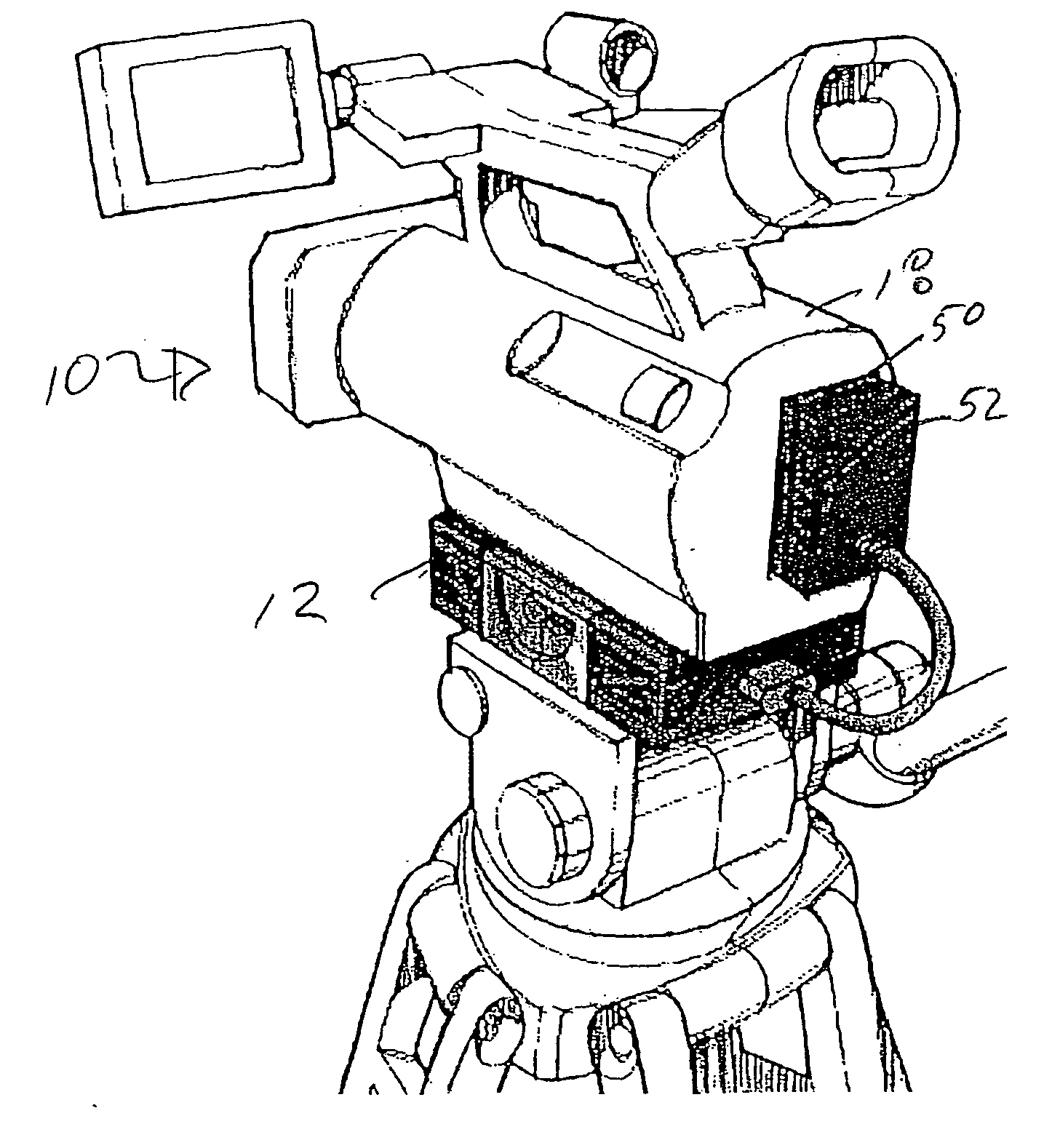
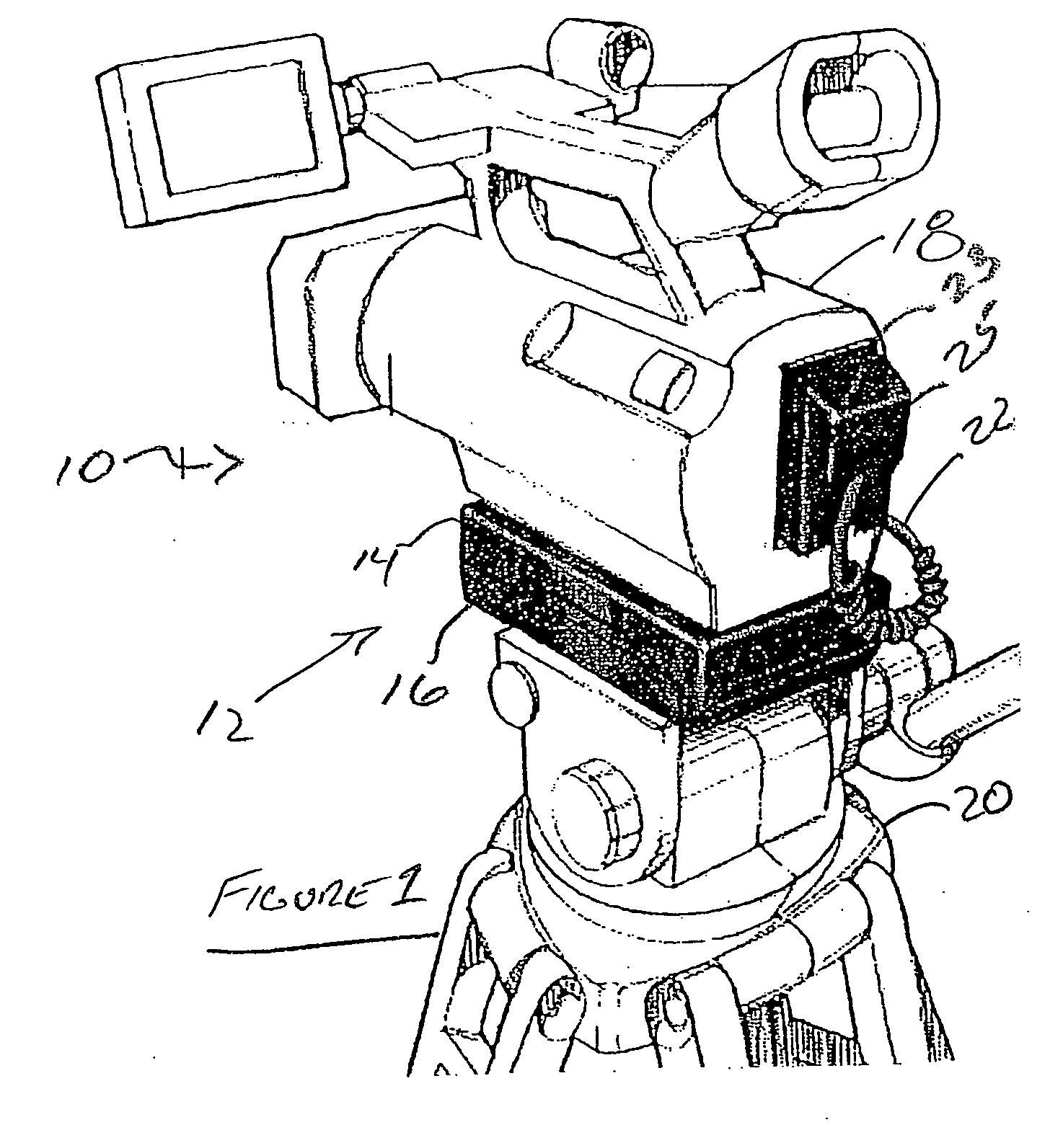
[0050] Known video cameras, both the hand-held variety and the larger, professional video cameras, are known to have a bottom, planar surface that is devoid of any structural or operational features, with the exception of a threaded bore and a positioning hole. It is also well known that the threaded bore and positioning hole that are defined on the bottom, planar surface of typical video cameras are utilized to mount the video cameras to pan and tilt heads / tripods. In practice, known pan and tilt heads / tripods are themselves equipped with a threaded stud, or the like, for selective and threaded engagement with the video camera's threaded bore, as well as having a location post for engagement with the positioning hole.

[0051] Despite the advancements in the video camera art over the years, which have added an ever-increasing host of additional features to video cameras, such as flip-out observation / preview screens, a plurality of editing buttons and the like, it will therefore be re...


PUM


Abstract

A camera system includes a video camera having a first mating mechanism defined on a bottom, planar surface of the video camera. A battery assembly contains an energy cell and a first surface of the battery assembly is releasably engageable with the mounting mechanism such that the battery assembly is suspended beneath the video camera, with the bottom, planar surface of the video camera in substantial contact with the first surface. A support apparatus having a second mating mechanism is also provided, the second mating mechanism releasably engaging a second surface of the battery assembly.

Description

CROSS-REFERENCE TO RELATED APPLICATIONS [0001] This application claims the benefit of U.S. Provisional Application No. 60 / 716,017, filed Sep. 9, 2005, entitled “BATTERY MOUNTING SYSTEM” and U.S. Provisional Application No. 60 / 716,625, filed Sep. 13, 2005, entitled “BATTERY MOUNTING SYSTEM”, each of the aforementioned applications being hereby incorporated by reference in their entireties.FIELD OF THE INVENTION [0002] This invention relates, in general, to an ergonomic camera system and power supply for optical recording devices, and deals more particularly with a method and apparatus for providing increased power capability and operability to video cameras. BACKGROUND OF THE INVENTION [0003] Technological advances in recording digital video, recording media, and electronics have led to video cameras of smaller size and weight. These smaller “hand-held” video cameras are replacing “shoulder mounted” video cameras of nearly 6 times the volume and weight. A typical “handheld” video cam...

Claims


Application Information

Patent Timeline
Patent Type & Authority Applications(United States)
IPC IPC(8): H04N5/225
CPCG03B17/56H04N2201/0084H04N1/00127H04N1/00493H04N1/00519H04N1/00557H04N1/00559H04N1/00562H04N1/00901H04N1/00907H04N1/2112H04N5/225H04N5/2251H04N2101/00H04N2201/0041H04N2201/0056H04N2201/0063G03B2217/007H04N23/50H04N23/00
Inventor DESORBO, ALEXANDER P.
Owner ANTONBAUER
Why Eureka
Try Eureka