
Process for producing embossed products

Inactive Publication Date: 2005-11-10
THE PROCTER & GAMBLE COMPANY
View PDF68 Cites 30 Cited by
  • Summary
  • Abstract
  • Description
  • Claims
  • Application Information

AI Technical Summary

Benefits of technology

[0046] The resulting embossed web 100 can have embossments of any shape, pattern, density and height. One advantage of the present invention is that it provides a method that is suitable for providing the web 100 with embossments with relatively high embossment heights, as compared to typical embossed webs. Accordingly, the apparatus and method of the present invention can provide embossments of any height, including, but not limited to webs with an average embossment height of at least about 650 μm. Other embodiments may have embossment having embossment heights greater than 1000 μm, greater than about 1250 μm, greater than about 1450 μm, at least about 1550 μm, at least about 1800 μm, between about 650 μm and about 1800 μm, at least about 2000 μm, at least about 3000 μm, at least about 4000 μm, between about 650 μm and about 4000 μm or any individual number within this range. The average embossment height is measured by the Embossment Height Test Method using a GFM MikroCAD optical profiler instrument, as described in the Test Method section below.
[0047] In certain embodiments, as shown, for example, in FIG. 4, at least some of the first embossing elements 50 and / or the second embossing elements 60, may have at least one transition region 85 that has a radius of curvature r. The transition region 85 is disposed between the distal end of the embossing element and the sidewall of the embossing element. (As can be seen in FIG. 4, the distal end of the first embossing element 50 is labeled 52, while the sidewall of the first embossing element 50 is labeled 54. Similarly, the distal end of the second embossing element 60 is labeled 62, while the sidewall of the second embossing element 60 is labeled 64.) The radius of curvature r is typically greater than about 0.075 mm. Other embodiments have radii of curvatures greater than 0.1 mm, greater than 0.25 mm, greater than about 0.5 mm, between about 0.075 mm and about 0.5 mm or any number within this range. The radius of curvature r of any particular transition regions is typically less than about 1.8 mm. Other embodiments may have embossing elements with transition regions 130 have radii of curvatures less than about 1.5 mm, less than about 1.0 mm, between about 1.0 mm and about 1.8 mm or any number within the range. (Although FIG. 4 shows an example of two intermeshing embossing plates, embossing plate 70 and embossing plate 80, the information set forth herein with respect to the embossing elements 50 and 60 is applicable to any type of embossing platform or mechanism from which the embossing elements can extend, such as rolls, cylinders, plates and the like.)
[0048] The “rounding” of the transition region 85 typically results in a circular arc rounded transition region 85 from which a radius of curvature is easily determined as a traditional radius of the arc. The present invention, however, also contemplates transition region configurations which approximate an arc rounding by having the edge of the transition region 85 removed by one or more straight line or irregular cut lines. In such cases, the radius of curvature r is determined by measuring the radius of curvature of a circular arc that has a portion which approximates the curve of the transition region 85.
[0049] In other embodiments, at least a portion of the distal end of one or more of the embossing elements other than the transition regions 85 can be generally non-planar, including for example, generally curved. Thus, the entire surface of the embossing element spanning between the sidewalls 54 or 64 can be non-planar, for example curved. The non-planar surface can take on any shape, including, but not limited to smooth curves or curves, as described above, that are actually a number of straight line or irregular cuts to provide the non-planar surface. One example of such an embossing element is the embossing element 63 shown in FIG. 4.
[0050] Although not wishing to be bound by theory, it is believed that rounding the transition regions 85 or any portion of the distal ends of the embossing elements can provide the resulting paper with embossments that are more blunt with fewer rough edges. Thus, the resulting paper may be provided with a smoother and / or softer look and feel.
[0051] It should be noted that with respect to any of the methods described herein, the number of plies is not critical and can be varied, as desired. Thus, it is within the realm of the present invention to utilize methods and equipment that provide a final web product having a single ply, two plies, three plies, four plies or any other number of plies suitable for the desired end use. In each case, it is understood that one of skill in the art would know to add or remove the equipment necessary to provide and / or combine the different number of plies. Further, it should be noted that the plies of a multi-ply web product need not be the same in make-up or other characteristics. Thus, the different plies can be made from different materials, such as from different fibers, different combinations of fibers, natural and synthetic fibers or any other combination of materials making up the base plies. Further, the resulting web 225 may include one or more plies of a cellulosic web and / or one or more plies of a web made from non-cellulose materials including polymeric materials, starch based materials and any other natural or synthetic materials suitable for forming fibrous webs. In addition, one or more of the plies may include a nonwoven web, a woven web, a scrim, a film a foil or any other generally planar sheet-like material. Further, one or more of the plies can be embossed with a pattern that is different that one or more of the other plies or can have no embossments at all.

Problems solved by technology

While known laminating and embossing technologies have provided suitable multi-ply web products, the methods used to laminate and emboss webs, such as paper webs, may be inefficient or provide manufacturing difficulties if the manufacture of the web includes other converting steps such as, for example printing, calendaring, etc.
In such cases, for example, the embossing step in the manufacture of the web can make it difficult to print on the embossed web or otherwise provide an additive to the web in a particular location and / or at an even add-on amount.
Further, any manufacturing processes after the embossing step may reduce the effectiveness of the embossing step by, for example, reducing the height of the embossments or delaminating the web plies.
Further yet, attempting to laminate the plies of a multi-ply web during an embossing step can reduce line speed potential, contaminate equipment and provide a web that has unintended lamination characteristics.

Method used


Image

  • Process for producing embossed products
  • Process for producing embossed products
  • Process for producing embossed products

Examples


Embodiment Construction

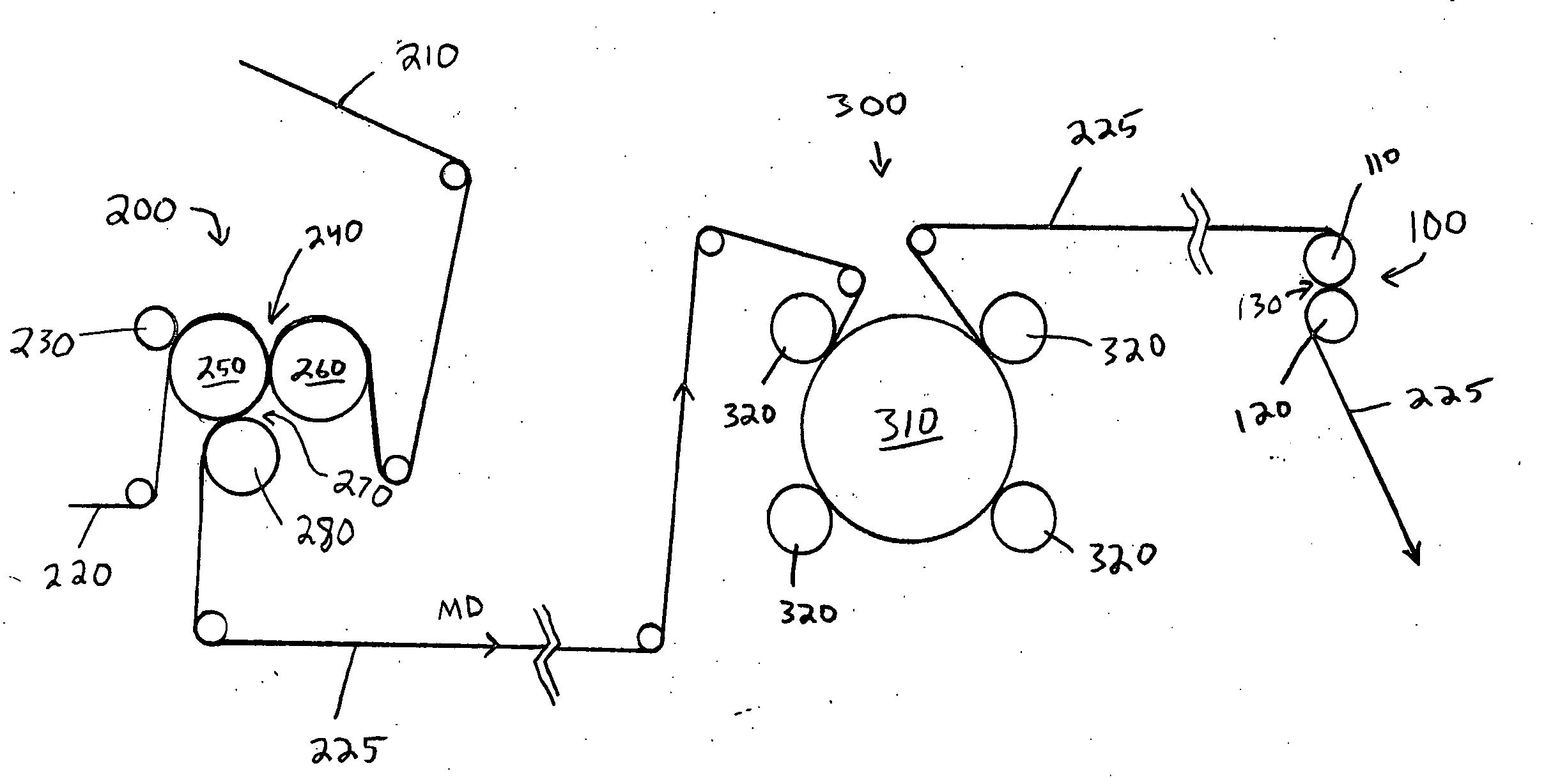
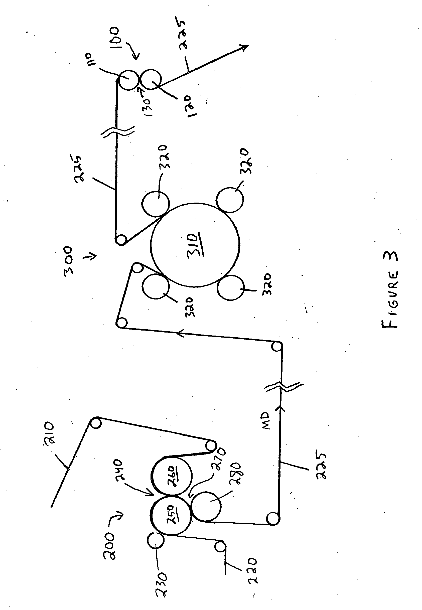
[0013] It has been discovered that a new laminating and embossing method may provide improvements in embossing processes and the webs that are subjected to such embossing processes. In particular, it has been found that it may be advantageous to separate the lamination step and the embossing steps when embossing a multi-ply web product, such as a paper product. Such separation of the lamination and embossing steps is particularly preferred when the web is to be printed and or when the web includes at least one low density ply, such as, for example, a ply of through-air-dried paper.

[0014] As used herein, the term “through-air dried” or “TAD” when referring to a paper (or other) web means that the web has been subjected to a through-air-drying process where air is passed through the web to remove moisture from the web. Examples of TAD equipment, processes and structures formed by TAD processes are described in more detail in U.S. Pat. No. 3,301,746 issued Jan. 31, 1967 to Sanford et a...


PUM

PropertyMeasurementUnit
Fractionaaaaaaaaaa
Fractionaaaaaaaaaa
Fractionaaaaaaaaaa

Abstract

A method for producing a multi-ply embossed product including the steps of: providing two or more plies of material to a lamination apparatus, each ply having a lamination surface; laminating one ply of the two or more plies of material to at least one other of the two or more plies of material to provide a laminated web having a first lamination pattern; directing the laminated web to a separate embossing apparatus; and embossing the laminated web in a second pattern to provide an embossed web, wherein the embossing step takes place after the laminated web is laminated.

Description

FIELD OF THE INVENTION [0001] The present invention relates to an improved apparatus and process for producing embossed web products and more particularly to embossed laminated web products. BACKGROUND OF THE INVENTION [0002] The embossing of webs, such as paper webs, is well known in the art. Embossing of webs can provide improvements to the web such as increased bulk, improved water holding capacity, improved aesthetics and other benefits. Both single ply and multiple ply (or multi-ply) webs are known in the art and can be embossed. Multi-ply paper webs are webs that include at least two plies superimposed in face-to-face relationship to form a laminate. [0003] During the embossing process, the web is typically fed through a nip formed between juxtaposed generally axially parallel rolls. Embossing elements on the rolls compress and / or deform the web to provide embossments to the web. Different embossing processes are known, but typically either “knob-to-knob” embossing or “nested”...

Claims


Application Information

Patent Timeline
IPC IPC(8): B31F1/07B31F1/12B32B37/20B32B38/06
CPCB31F1/07B31F2201/0738B31F2201/0743B31F2201/0756B31F2201/0764Y10T156/1023B31F2201/0787B31F2201/0792B32B37/20B32B38/06B32B38/14B31F2201/0774
Inventor KRAUS, CHRISTOPHER SCOTTSTELLJES, MICHAEL GOMER JR.WEGELE, GEORGE VINCENTJEROME WILKE, NICHOLAS IICLIFFORD NOLL, JOSEPHRUSSELL, MATTHEW ALANFISHER, WAYNE ROBERTRASCH, DAVID MARK
Owner THE PROCTER & GAMBLE COMPANY
Learn More