
Roller seat, and carrier for a very-large-capacity tool and material holder also mountable atop a step ladder

Inactive Publication Date: 2005-11-10
HEDKELLEY
View PDF4 Cites 4 Cited by
  • Summary
  • Abstract
  • Description
  • Claims
  • Application Information

AI Technical Summary

Benefits of technology

[0028] The tool holder is removably mountable to the top of a step ladder, and is in the substantial shape of a frustum having an open base. The toll holder serves to hold tools and like implements, and paint cans and like supplies, for use by painters and electricians and other individuals when, in the course of their work, these persons stand on upon the step ladders. In accordance with related inventions, a particular tool holder is both versatile and convenient for each of (1) carrying and (2) organizing and (3) holding various work supplies and work implements by dint of incorporating (a) variably sized and distending pockets, (b) variable numbers of pockets, and / or (c) attachable pockets and / or holders tailored to the particular tools or materials sought to be held.
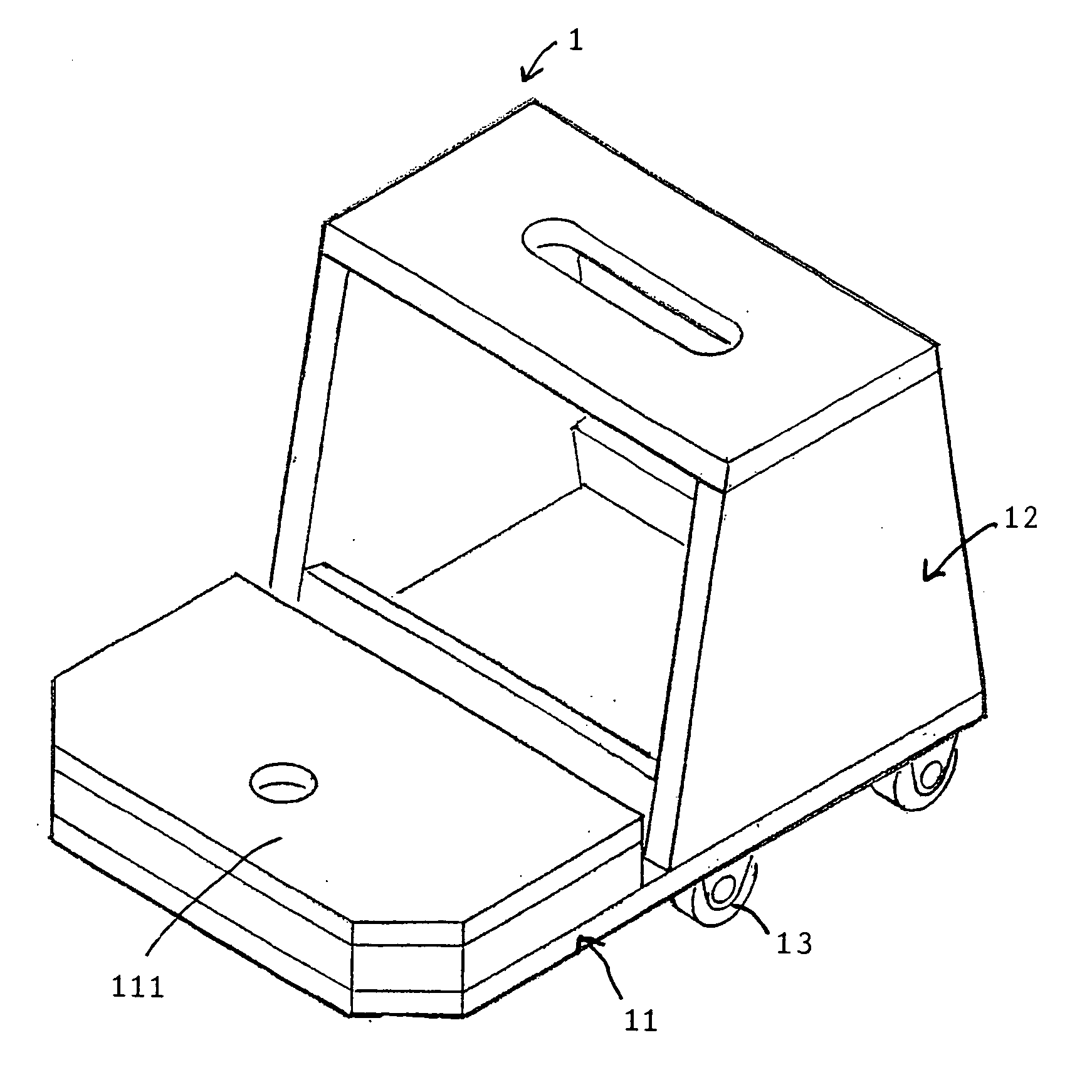
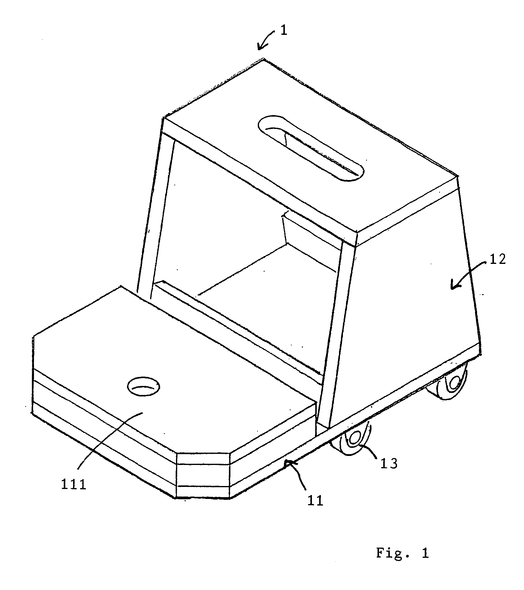
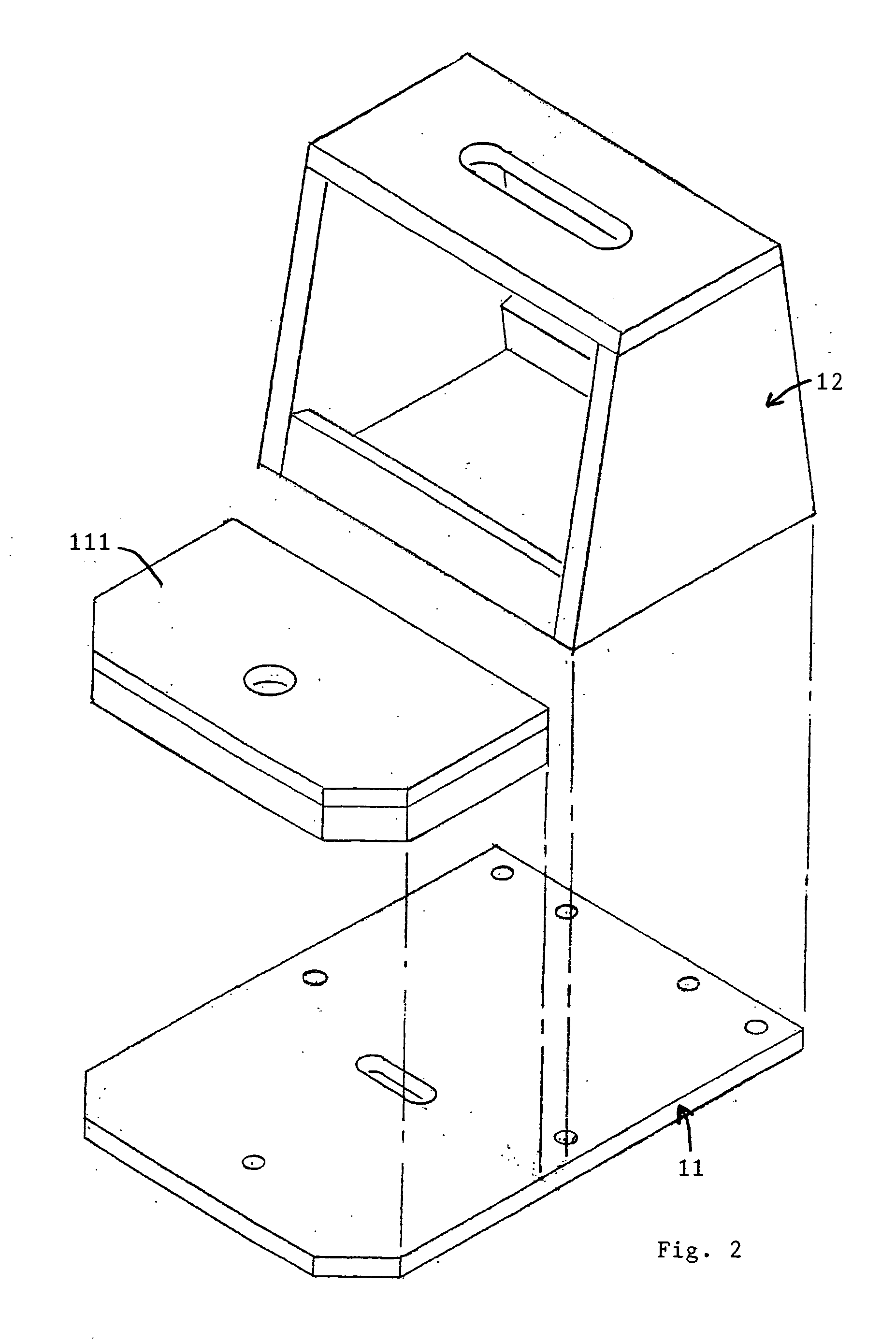
[0039] The combination roller seat and carrier preferably further includes posts extending downwards from the base. These posts serve, in combination with the wheels, to prevent that the combination roller seat and carrier should tip over nonetheless that holder, and any tools and materials held by the holder, be attached to the frustum structure.

Problems solved by technology

Time and motion observations of, in particular, persons working at high and at low elevations on walls—such as dry wallers and carpenters and painters—either have to (1) carry upon their person a sometimes inordinate amount of tools and materials (which is naturally tiring), or else (2) hazard that some tool, or some material, wanted at one position is unfortunately located at another position (necessitating transition, which is also tiring).

Method used


Image

  • Roller seat, and carrier for a very-large-capacity tool and material holder also mountable atop a step ladder
  • Roller seat, and carrier for a very-large-capacity tool and material holder also mountable atop a step ladder
  • Roller seat, and carrier for a very-large-capacity tool and material holder also mountable atop a step ladder

Examples


Embodiment Construction

[0056] The following description is of the best mode presently contemplated for the carrying out of the invention. This description is made for the purpose of illustrating the general principles of the invention, and is not to be taken in a limiting sense. The scope of the invention is best determined by reference to the appended claims.

1. Objects of the Invention

[0057] In accordance with the shortcomings contained in the prior art, it is an object of the present invention to provide a convenient device through the use of which building tradesmen may extend the use of a tool and material caddy used atop a step ladder to floor level, thereby to minimize the number of up-and-down ladder trips required to do the same, or like, tasks with the same, or like, tools using the same, or like materials, at both elevated and floor levels.

[0058] It is an object of this invention to provide a means for caddying tools and materials used by building tradesmen from ladder to ladder, and / or to t...


PUM


Abstract

A combination (i) roller seat and (ii) tool and material carrier is preferably used with a hollow body tool and material holder detachably mountable to the upper region of an open step ladder. The combination roller seat and carrier has a substantially planar base with a structure in the shape of a truncated frustum attached to and extending above the base, this structure occupying a same shape and volume as does a truncated frustaconical upper region of a open step ladder. Wheels to the base permit a person to sit upon the top of the structure while the base rolls upon the wheels, making thereby a roller seat. When the hollow body tool and material holder detachably mountable to the upper region of the open step ladder is alternatively mounted over the structure, the structure serves at least indirectly to hold any tools and materials that are also held by this hollow body holder.

Description

RELATION TO RELATED PATENT APPLICATIONS [0001] The present patent application is related as a continuation-in-part to U.S. patent application Ser. No. 09 / 735,029 filed on Dec. 11, 2000 for a FLEXIBLE TRUNCATED-PYRAMIDALLY-SHAPED TOOL AND MATERIAL HOLDER WITH A DISTENDED PAINT PAIL POUCH FOR REMOVABLE USE ATOP A STEP LADDER now issued as U.S. Pat. No. 6,654,941, and also to Ser. No. 10 / 074,058 filed on Feb. 11, 2002, for a FREE-STANDING VERY-LARGE-CAPACITY FLEXIBLE MODULAR TOOL AND MATERIAL HOLDER SELECTIVELY MOUNTABLE ATOP A STEP LADDER. Both prior applications are to the same inventor as the present application. The contents of the related predecessor patent and patent application are incorporated herein by reference.BACKGROUND OF THE INVENTION [0002] 1. Field of the Invention [0003] The present invention generally concerns roller trucks and caddys as are commonly used by mechanics and other craftsman to sit upon, and to hold tools and / or materials, during the course of their work....

Claims


Application Information

Patent Timeline
IPC IPC(8): B25H3/00B25H3/02B25H3/06B65D85/28E06C1/397E06C7/14
CPCB25H3/00B25H3/02E06C7/14E06C1/397B25H3/06
Inventor HEDGES, KELLEY
Owner HEDKELLEY
Learn More