Apparatus for removing material from a liquid flowing through a channel

a technology of liquid flowing through a channel and a material removal device, which is applied in the direction of moving filter element filters, separation processes, filtration separation, etc., can solve the problems of reducing the efficiency of the process, the inability of the known apparatus to treat sludge-like screening devices, and the design limitation is constructive, so as to achieve the effect of improving the pre-dewatering effect, reducing the cost of production, and reducing the size of the opening

Inactive Publication Date: 2005-11-10
HANS HUBER MASCHEN & ANLAGENBAU
View PDF14 Cites 8 Cited by
  • Summary
  • Abstract
  • Description
  • Claims
  • Application Information

AI Technical Summary

Benefits of technology

[0022] The mesh fabric may be especially a square meshes fabric having a mesh aperture between approximately 0.2 mm and 1.2 mm. Such square mesh fabrics may be manufactured economically on looms. The mesh aperture may be kept constant in narrow regions, and it allows for an individual adaptation with respect to the size of the particles of the sludge-like screenings. Consequently, screenings in form of fibers, hairs and the like can be removed without difficulty.
[0023] The feeding hopper perforated at its bottom may include bores with a diameter of approximately 2 mm. Bores of this size do not prevent screening of sludge-like material. The screenings deposited with the fine mesh fabric will agglomerate during detaching, and they enter the feeding hopper. Bores of this size are very effective to reach an improved pre- dewatering effect in the feeding hopper.

Problems solved by technology

Smaller openings cannot be produced economically.
Consequently, the known apparatus cannot be used to treat sludge-like screenings.
There are constructive limits in the design due to the formation of the openings of the sieve grate in form of the number of ring-like discs.
Sludge cannot be screened using the known apparatus.

Method used


Image

  • Apparatus for removing material from a liquid flowing through a channel
  • Apparatus for removing material from a liquid flowing through a channel
  • Apparatus for removing material from a liquid flowing through a channel

Examples


Embodiment Construction

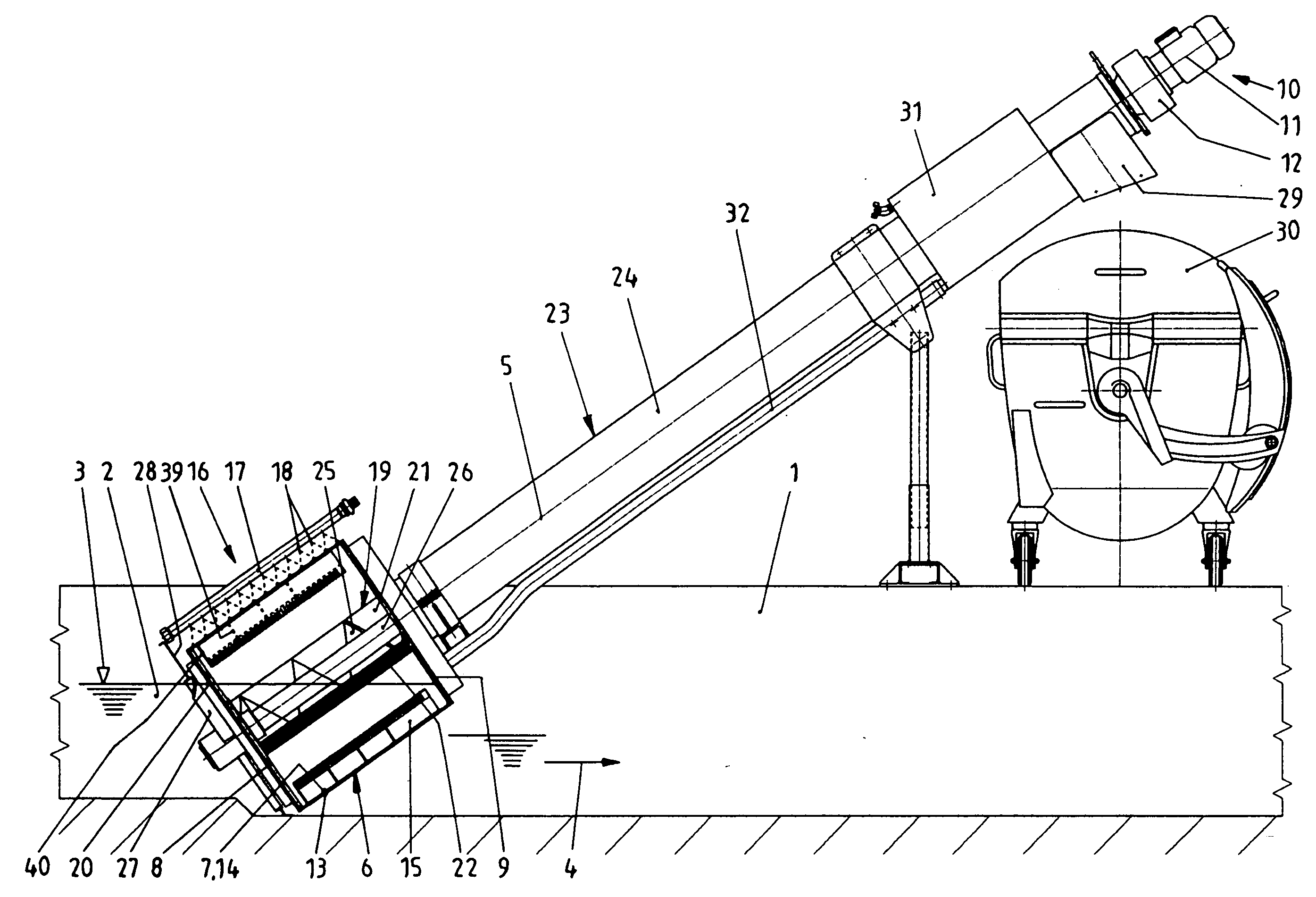
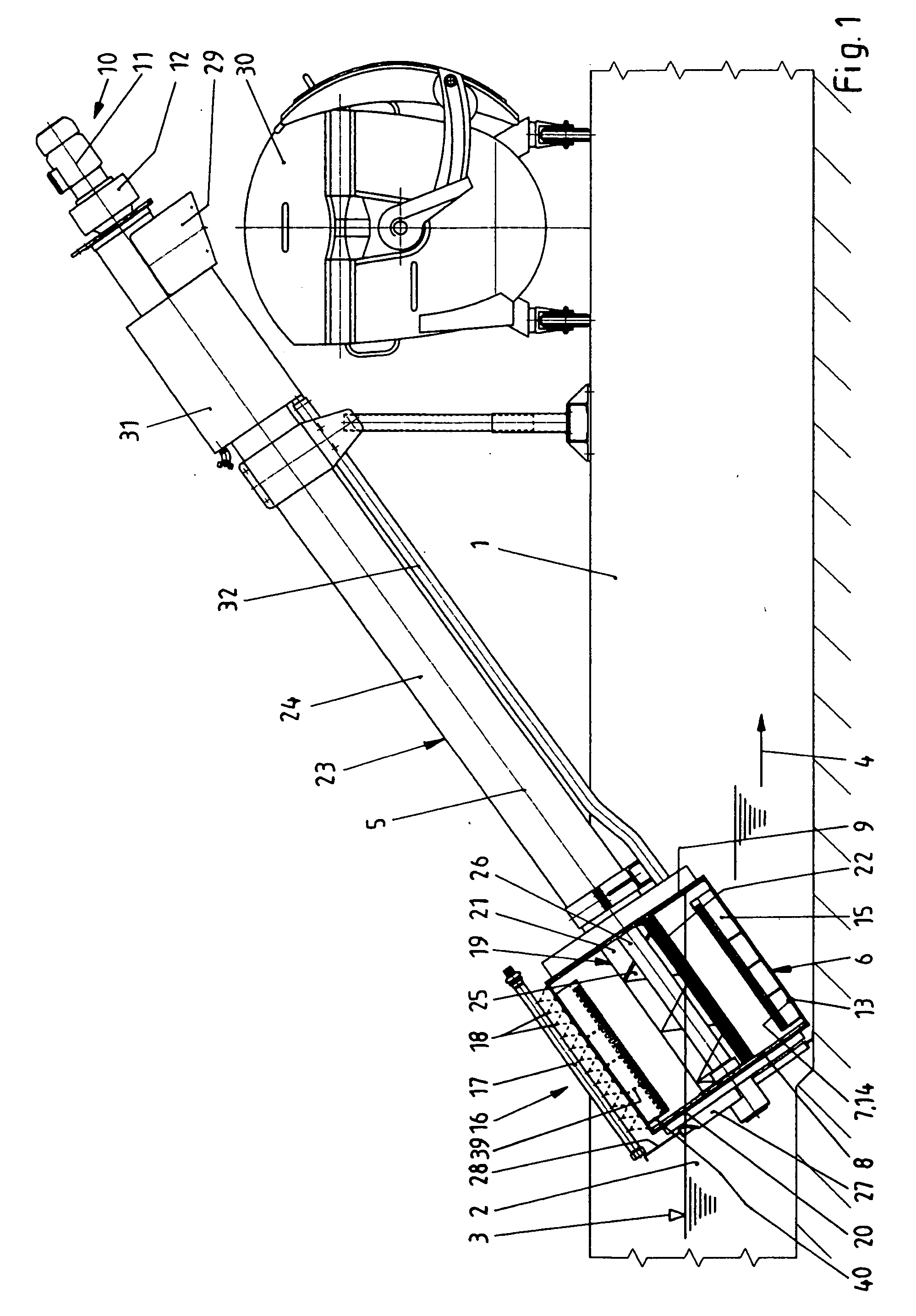
[0034] Referring now in greater detail to the drawings, FIG. 1 shows a part of a channel 1 in which a liquid 2 contaminated with material to be screened and having a water level 3 is flowing in the direction of arrow 4.

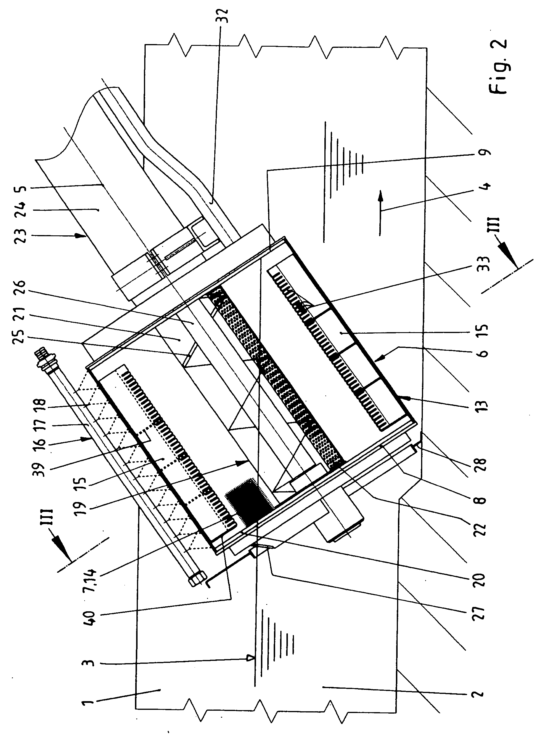
[0035] The novel apparatus for removing material from the liquid 2 flowing through the channel 1 is located in the channel 1 such that its axis 5 is arranged in a inclined manner. Preferably, the angle of inclination is approximately 35°. However, other angles of inclination are also possible. The apparatus includes a cylindrical sieve grate 6 including a mesh fabric 7. The sieve grate 6 has an open front side 8 on the inflow side thereof, the contaminated liquid 2 flowing through the open front side 8 into the interior of the sieve grate 6. A sealed and thus hydraulically closed back side 9 is located downstream. The sieve grate 6 is rotatably arranged near the back side 9, and it is sealed with respect to elements not rotating. The sieve grate 6 is rotatably driven...


PUM

PropertyMeasurementUnit
diameteraaaaaaaaaa
sizeaaaaaaaaaa
sizeaaaaaaaaaa

Abstract

An apparatus for removing material from a liquid flowing through a channel includes a sieve grate, a screw conveyor and a detaching device. The sieve grate has an inflow side, an inner side and an outer side. The sieve grate is designed to be cylindrical and to be rotatably driven. The sieve grate is arranged at an inclined orientation to be partially submerged in the liquid. The sieve grate at the inflow side includes an open face. The sieve grate at the inner side includes a plurality of guide plates. The sieve grate includes a shaping carrier element. The sieve grate includes a mesh fabric, the mesh fabric being designed and arranged to form a separation surface for the material. The screw conveyor includes a housing. The screw conveyor includes a driven conveying screw. The screw conveyor is coaxially arranged with respect to the sieve grate. The screw conveyor in the region of the sieve grate includes a feeding hopper for the material, the feeding hopper having a bottom side and including a majority of openings located in the region of the bottom side. The detaching device is arranged at the outer side of the sieve grate and above the feeding hopper in a stationary way. The detaching device is designed and arranged to detach material which adheres to the separation surface from inside of the sieve grate.

Description

CROSS REFERENCE TO RELATED APPLICATIONS [0001] This application is a continuation of International Application PCT / EP2004 / 00387 with an international filing date of Jan. 20, 2004 claiming priority to co-pending German Patent Application No. DE 103 02 494.8 entitled “Vorrichtung zum Entfernen von Siebgut aus in einem Gerinne strömender Flössigkeit”, filed on Jan. 23, 2003.FIELD OF THE INVENTION [0002] The present invention generally relates an apparatus for removing material from a liquid flowing through a channel. [0003] More particularly, the present invention relates to an apparatus for cleaning waste water including a rotatably driven sieve grate, a screw conveyor and a detaching device. With such an apparatus, especially screenings or rakings are removed from a liquid flowing in a channel. BACKGROUND OF THE INVENTION [0004] An apparatus device for removing material from a liquid flowing through a channel is known from German Patent No. DE 34 20 157 C1 corresponding to U.S. Pat. ...

Claims


Application Information

Patent Timeline
Patent Type & Authority Applications(United States)
IPC IPC(8): B01D29/03B01D33/11E03F5/14
CPCB01D29/035B01D33/11E03F5/14B01D29/6476B01D29/68B01D33/50B01D33/76
Inventor FROMMANN, CHRISTIAN
Owner HANS HUBER MASCHEN & ANLAGENBAU
Why Eureka
Try Eureka