Water treatment system

Inactive Publication Date: 2005-11-10
FRANKLIN ELECTRIC CO INC
View PDF29 Cites 31 Cited by
  • Summary
  • Abstract
  • Description
  • Claims
  • Application Information

AI Technical Summary

Benefits of technology

[0005] One form of the present invention contemplates a water treatment system, comprising: a tank having a top and a bottom; a control valve located at the top and in fluid communication with the tank, the control valve including a source water inlet adapted to be coupled to a source of water, a drain outlet, a treated water outlet and an air inlet, the air inlet is in fluid flow communication with a v

Problems solved by technology

These mineral contaminates may cause stained plumbing fixtures and corroded pipes and in add

Method used


Image

  • Water treatment system
  • Water treatment system
  • Water treatment system

Examples


Embodiment Construction

[0028] For purposes of promoting an understanding of the principles of the invention, reference will now be made to the embodiments illustrated in the drawings and specific language will be used to describe the same. It will nevertheless be understood that no limitation of the scope of the invention is thereby intended, such alterations and further modifications in the illustrated device, and such further applications of the principles of the invention as illustrated therein being contemplated as would normally occur to one skilled in the art to which the invention relates.

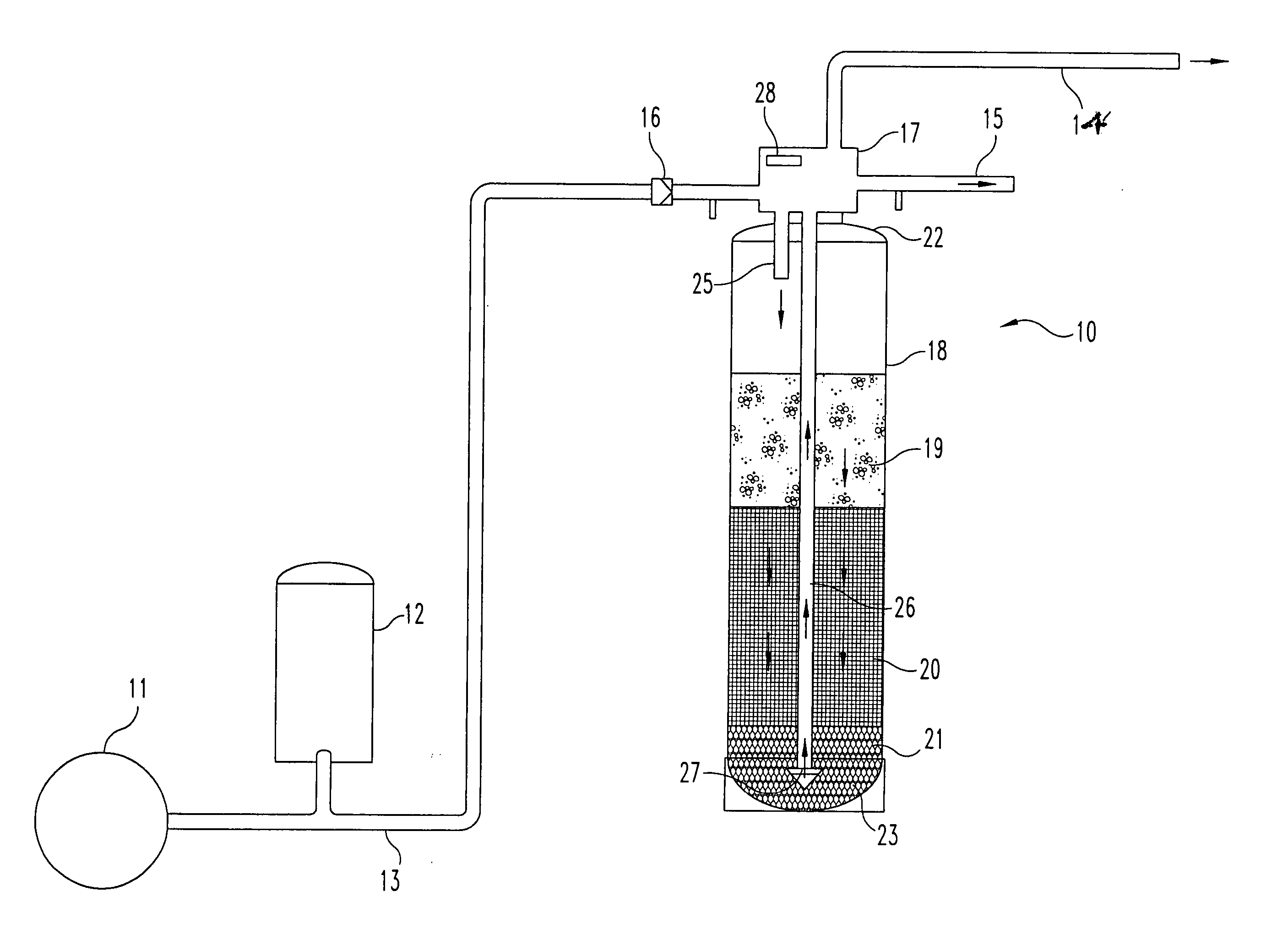
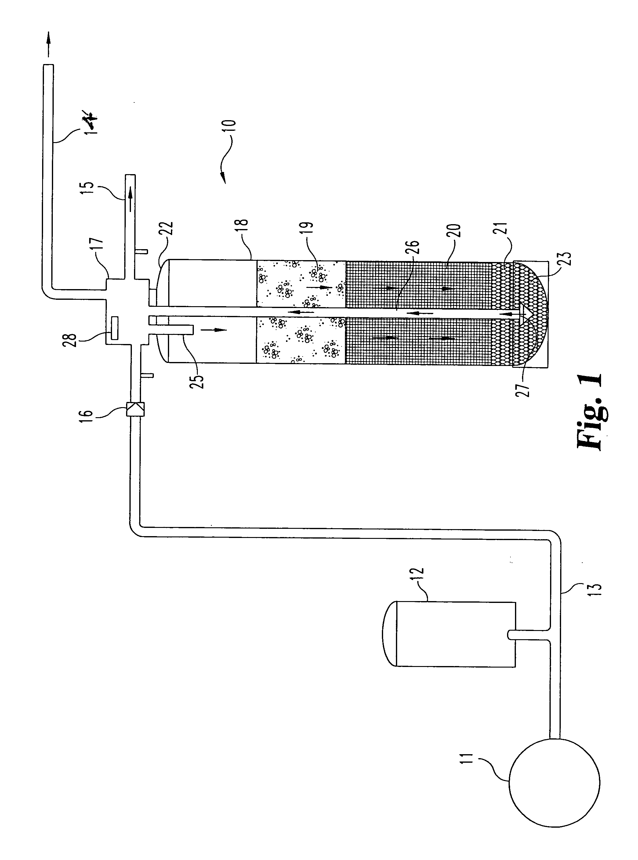
[0029] With reference to FIG. 1, there is schematically illustrated a water treatment system 10 in fluid communication with a water source 11. The water treatment systems contemplated herein are designed to remove / control iron, sulfur, methane gas, and odor from water supplies. The water treatment system 10 will be generally referred to as a single stage air induction filter system. Water source 11 may be a well,...


PUM

PropertyMeasurementUnit
Diameteraaaaaaaaaa
Diameteraaaaaaaaaa
Flow rateaaaaaaaaaa

Abstract

A water treatment system which includes a control valve with a venturi for drawing air into a tank. The passage of untreated water into the control valve draws air into a tank for oxidation of the water. The flow of the air into the tank is independent of the flow of treated water from the system.

Description

BACKGROUND OF THE INVENTION [0001] The present invention relates generally to water treatment systems for removing contaminants from a water supply prior to delivery to an end user. More particularly, in one form the present invention relates to a water treatment system utilizing a venturi to draw air into a treatment tank independently of the passage of treated water to the end user. [0002] It is well recognized that most well water contains many contaminants. Common naturally occurring contaminants in well water include iron, sulfur, and manganese. These mineral contaminates may cause stained plumbing fixtures and corroded pipes and in addition, may result in the presence of disagreeable odors and an unpleasant taste in the water. [0003] Many different water treatment systems have been developed over the years in attempts to remove contaminants from water supplies. These water treatment systems have been utilized for municipal water systems and individual well systems. It is gener...

Claims


Application Information

Patent Timeline
IPC IPC(8): C02F1/00C02F1/28C02F1/74
CPCC02F1/001C02F1/006C02F1/008C02F2303/16C02F1/283C02F1/74C02F1/281
Inventor PETTY, BRET L.
Owner FRANKLIN ELECTRIC CO INC
Why Eureka
Try Eureka