Adjustable screw foot for appliances

Inactive Publication Date: 2005-11-10
MIELE & CO KG
View PDF9 Cites 47 Cited by
  • Summary
  • Abstract
  • Description
  • Claims
  • Application Information

AI Technical Summary

Benefits of technology

[0008] It is a primary object of the invention to provide a feature which wo

Problems solved by technology

The disadvantage of this prior art feature is believed to be that the height of its foot can only be adjusted by a sprocket connected to an adjustment rod.
It i

Method used


Image

  • Adjustable screw foot for appliances
  • Adjustable screw foot for appliances
  • Adjustable screw foot for appliances

Examples


Embodiment Construction

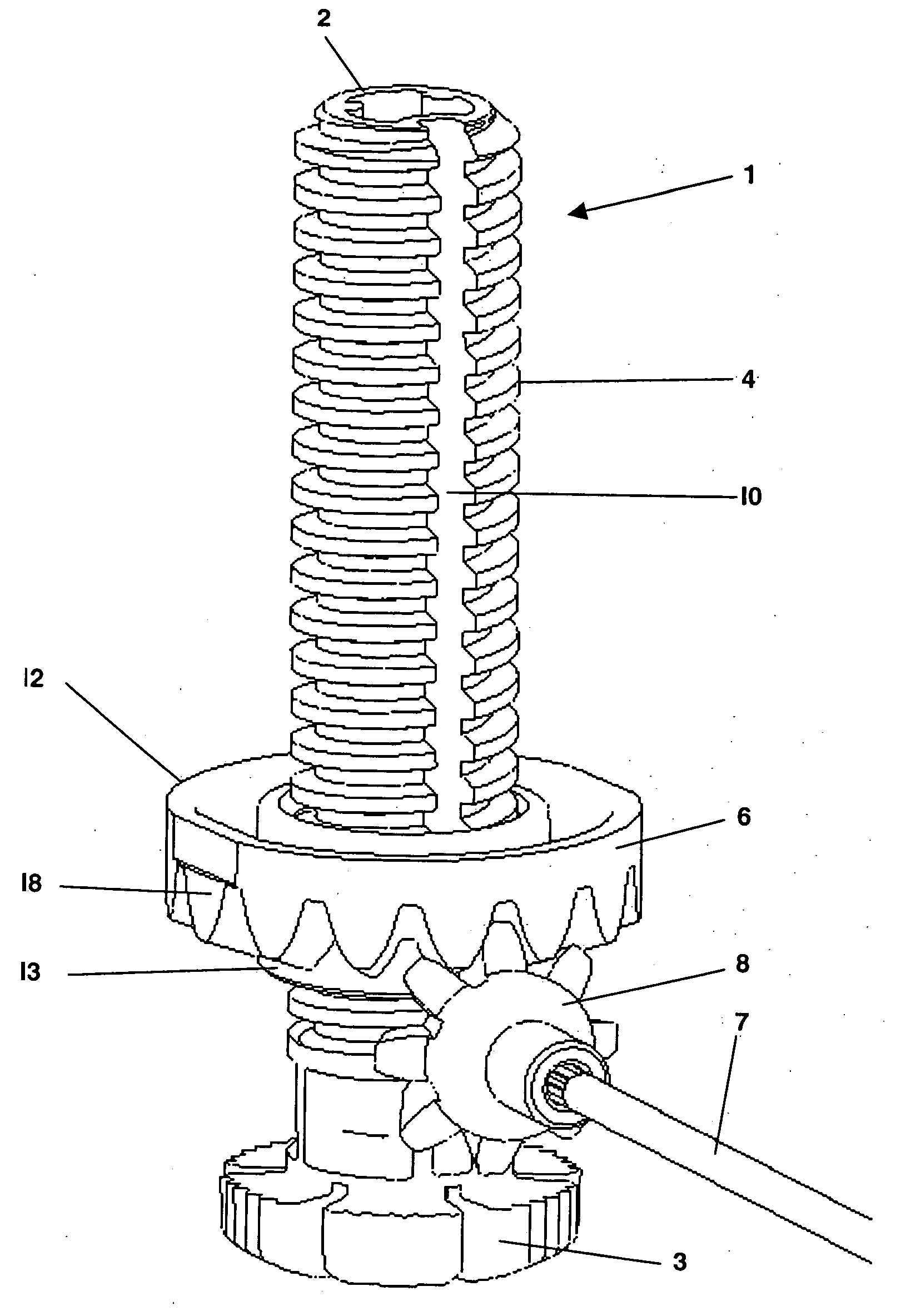
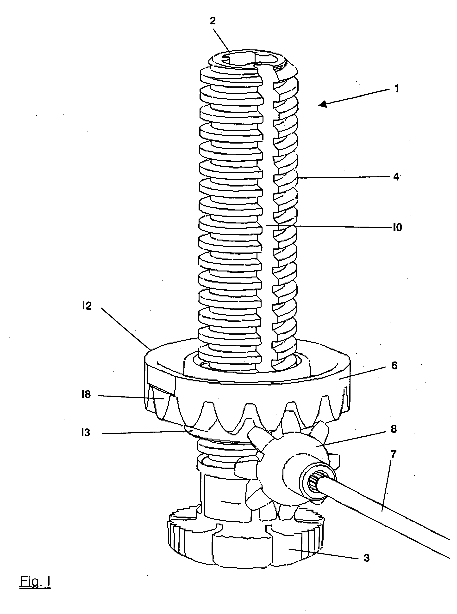
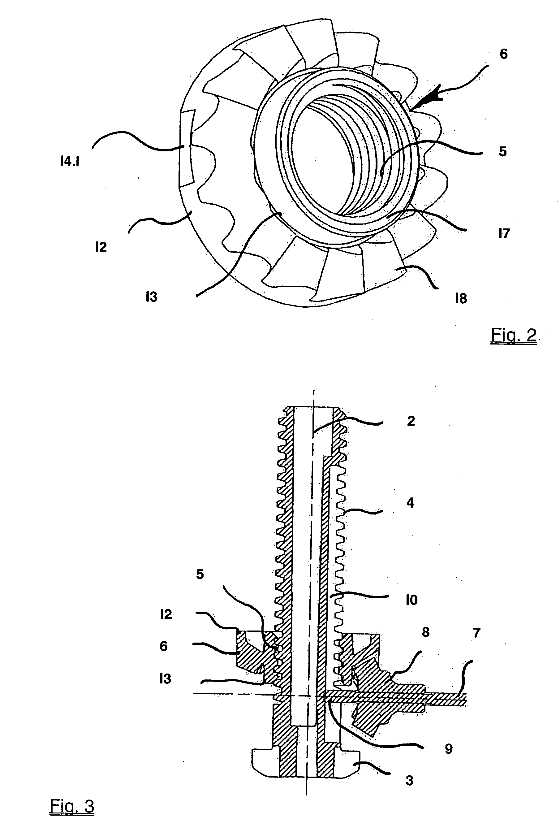
[0023]FIG. 1 is an isolated representation of an adjustable foot 1 for household appliances, such as, for instance, washing machines or dishwashers, constituted by a shank 2 which, as shown in FIG. 1, at its free end is provided with an integral support disc 3. As shown in FIG. 1, the exterior of the shank 2 is provided over its longitudinal extent with a thread 4 which cooperates with an interior thread 5 of a sprocket 6. The sprocket 6 is shown in greater detail in FIG. 2 depicting the sprocket 6 in perspective. As shown, the teeth of the sprocket 6 are cut into one of its axial surfaces. The opposite plane axial surface of the sprocket 6 engages a plane surface of the housing of the appliance (not shown), and its teeth mesh with a toothed gear 8 affixed to an adjustment rod 7. Thus, rotating the gear 8 by way of the rod 7 causes the shank 2 of the foot 1 which is secured against rotating to move axially with respect to the housing of the appliance and, depending upon the directio...


PUM


Abstract

A foot for adjusting the height of an appliance such as, for instance, a dishwasher or washing machine, provided with a threaded shank and a sprocket seated thereon for rotation relative thereto. The sprocket may be shifted between a first orientation in which the shank may be rotated while the sprocket is secured against rotation to adjust the height of the appliance by translatory movement of the shank and a second orientation in which the sprocket may be rotated and the shank is secured against rotation but is free to move axially.

Description

BACKGROUND OF THE INVENTION [0001] 1. Field of the Invention [0002] The invention, in general, relates to a novel screw foot of the kind used for leveling, or adjusting the height of, household appliances such as, for instance, washing machines, dryers, dishwashers, refrigerators and the like (hereinafter sometimes collectively referred to as “appliance”) and, more particularly, to an adjustable screw foot provided with a shank which over its longitudinal extent is provided with a thread cooperating with the interior thread of a sprocket mounted for rotation relative to the appliance and operatively connected, by way of an adjustment rod, to a toothed gear such that motion of the toothed gear causes the rotationally secured shank of the foot to exercise a translatory movement. [0003] In household appliances and, more particularly, dishwashers, a distinction is made between so-called free-standing dishwashers and dishwashers integrated into wall cabinets of a kitchen or other suitabl...

Claims


Application Information

Patent Timeline
IPC IPC(8): A47L15/42D06F39/12F16M7/00
CPCA47L15/4253F16M7/00D06F39/125
Inventor THUELIG, MARKUS
Owner MIELE & CO KG
Why Eureka
Try Eureka