Phosphorescent phosphor powder, manufacturing method thereof and afterglow fluorescent lamp

a technology of fluorescent lamps and phosphorescent phosphor powder, which is applied in the direction of discharge tubes/lamp details, discharge tubes luminescnet screens, gas-filled discharge tubes, etc., and can solve the problem of lowering the light emission intensity of lamps

Inactive Publication Date: 2005-11-10
NEC CORP
View PDF2 Cites 27 Cited by
  • Summary
  • Abstract
  • Description
  • Claims
  • Application Information

AI Technical Summary

Benefits of technology

[0022] An afterglow fluorescent lamp according to the present invention has a structure wherein at least a phosphorescent phosphor layer is set on the internal surface of the container forming a discharge space, and therein pinholes can be prevented from appearing in the phosphorescent phosphor layer. An application of the present invention to an afterglow fluorescent lamp can prevent the pinhole formation therein, while an application to a rapid-start type fluorescence lamp in the mode of the conductive internal coating can suppress the formation of dark spots referred to as “sanding” in the phosphor layer thereof.

Problems solved by technology

Moreover, a lack of the phosphorescent phosphor layer in those sections of pinholes lowers the light emission intensity of the lamp.

Method used


Image

  • Phosphorescent phosphor powder, manufacturing method thereof and afterglow fluorescent lamp
  • Phosphorescent phosphor powder, manufacturing method thereof and afterglow fluorescent lamp

Examples


example 1

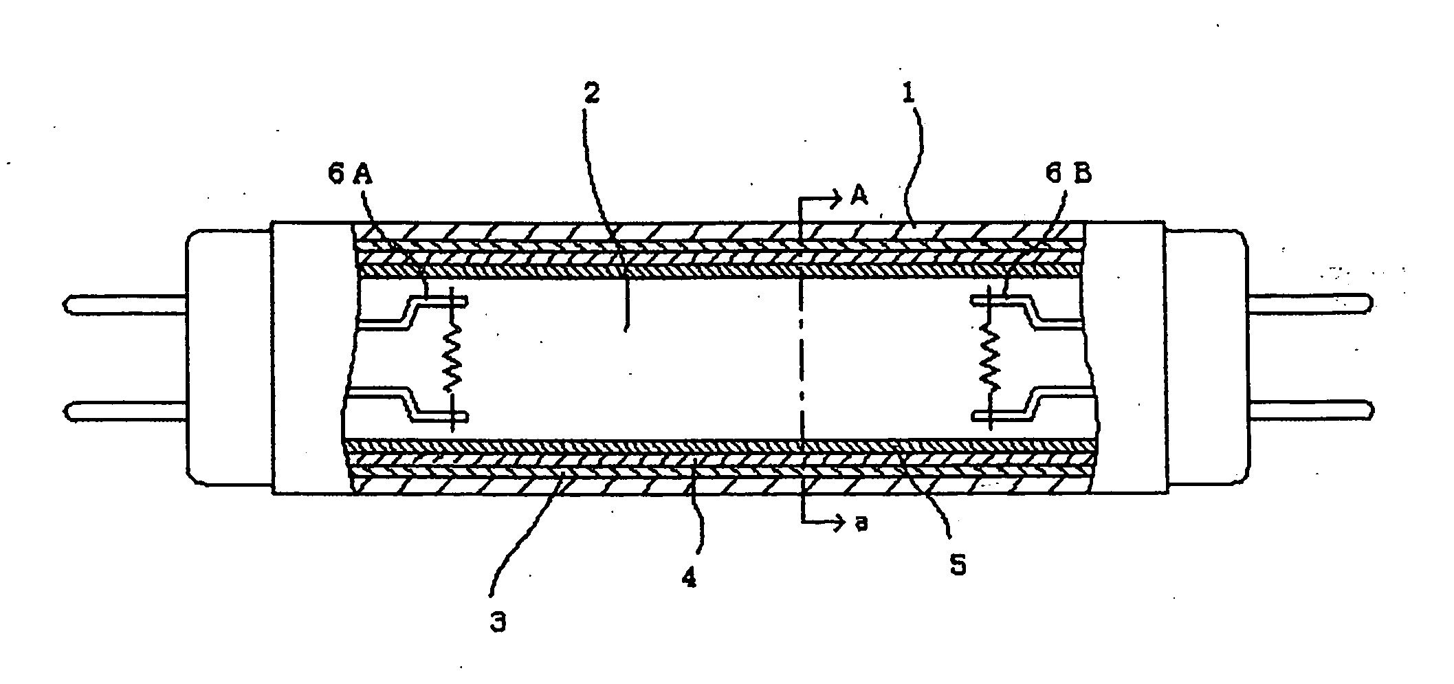
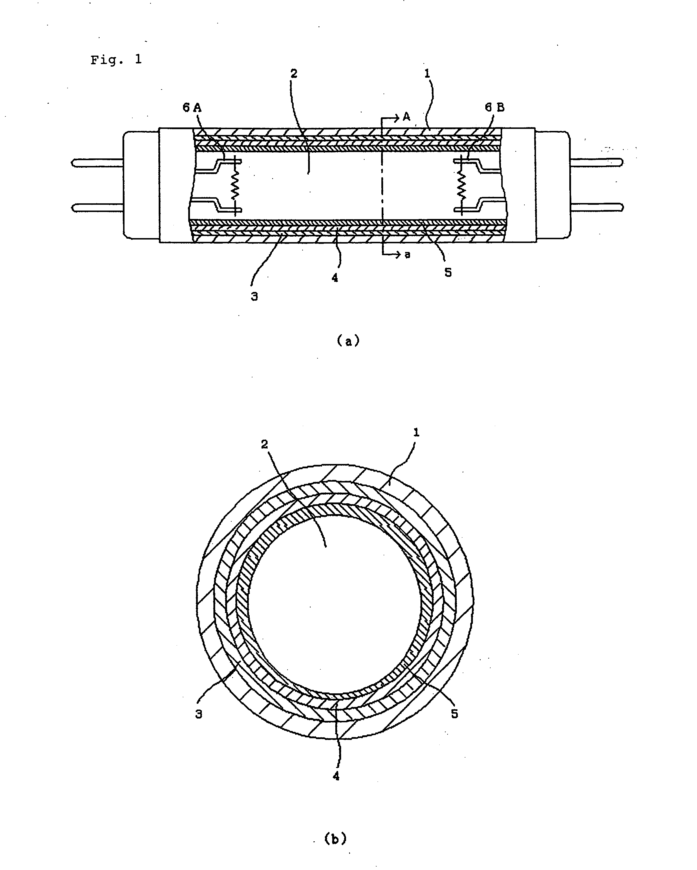
[0027] For a phosphorescent phosphor layer 4, there was used a layer in which α-alumina particles with a size distribution of 0.3 μm to 5 μm were mixed with phosphor particles of SrAl2O3: Eu, Dy having an average particle size of 10 μm and a particle-size distribution of 5 μm to 20 μm. As for the content of the α-alumina particles in the phosphorescent phosphor layer, three levels of the content ratio by weight, 10 wt %, 20 wt % and 40 wt % were chosen to use.

example 2

[0038] Afterglow fluorescent lamps each with the same structure as Example 1 were fabricated, using the same manufacturing method as Example 1 except that γ-alumina particles, instead of α-alumina particles, were contained in the phosphorescent phosphor layer 4.

[0039] The same test as performed in Example 1 was conducted for the fabricated lamps, and the same results as shown in Table 1 were obtained. Further, the effects of suppressing the sanding phenomenon were also obtained as Example 1.

example 3

[0040] Afterglow fluorescent lamps with the same structure as Example 1 were fabricated, using the same manufacturing method as Example 1 except that a mixed powder of α-alumina particles and γ-alumina particles, which were used in Example 1 and Example 2, respectively, were contained in the phosphorescent phosphor layer 4.

[0041] The same test as performed in Example 1 was conducted for the fabricated lamps, and the same results as shown in Table 1 were obtained. No difference in effects between lamps with different content ratios of α-alumina and γ-alumina was found. Further, the effects of suppressing the sanding phenomenon were also obtained as Example 1.

[0042] The reason why, in Examples 1 to 3, the addition of α-alumina particles, γ-alumina particles or a mixed powder of α-alumina particles and γ-alumina particles in the phosphorescent phosphor layer 4 suppressed the pinhole appearance is thought as follows.

[0043] As described above, mercury exists in liquid phase when the l...


PUM

PropertyMeasurementUnit
pressureaaaaaaaaaa
pressureaaaaaaaaaa
particle sizeaaaaaaaaaa

Abstract

In an afterglow fluorescent lamp having a structure wherein at least a phosphorescent phosphor layer is set on the internal surface of a glass container, pinholes are prevented from appearing in the layer. The layer is formed, using a phosphorescent phosphor powder, wherein a metal oxide powder whose primary particles have a particle-size distribution with an upper limit particle size smaller than a lower limit particle size of a particle-size distribution that primary particles of a matrix material of the phosphorescent phosphor powder have is mixed, in a ratio by weight that is not less than 10 wt % but not greater than 40 wt %, with the matrix material of the phosphorescent phosphor powder. Therein, the particles of the metal oxide fill the gaps among the particles of the phosphorescent phosphor, and thereby the adhesive strength between the particles of the phosphorescent phosphor is heightened.

Description

BACKGROUND OF THE INVENTION [0001] 1. Field of the Invention [0002] The present invention relates to a phosphorescent phosphor powder, a manufacturing method thereof and an afterglow fluorescent lamp, and more particularly to prevention of peeling-off of a phosphorescent phosphor layer in an afterglow fluorescent lamp wherein a phosphorescent phosphor is utilized. [0003] 2. Description of the Related Art [0004] The afterglow fluorescent lamp makes good use of characteristics (the phosphorescent natures or the long afterglow properties) that the phosphorescent phosphor has, that is, the capabilities to keep glowing persistently for a considerable time after the cessation of the stimulus. Since the lamp remains luminous even after the external power supply is cut off, it is used in the space where a large number of people gather, for instance, a large-sized store, a theater or an underground shopping complex for the general lighting and, at the same time, for the means to indicate the...

Claims


Application Information

Patent Timeline
Patent Type & Authority Applications(United States)
IPC IPC(8): C09K11/02C09K11/55C09K11/08C09K11/64C09K11/67C09K11/77C09K11/78C09K11/80C09K11/84H01J1/62H01J61/00H01J61/35H01J61/44H01J61/46H01J61/54
CPCC09K11/02C09K11/7792H01J61/545H01J61/44H01J61/46H01J61/35H01J61/42H01J61/48
Inventor NOMURA, KOJIISHIBASHI, KENJI
Owner NEC CORP
Why Eureka
Try Eureka