Current transformer with rogowski type windings, comprising an association of partial circuits forming a complete circuit

a current transformer and rogowski-type technology, applied in transformers/inductance coils/windings/connections, instruments, inductances, etc., can solve problems such as large measurement errors, disturbance of uniformity, electrical and mechanical junction zones between two adjacent pcb quarters, etc., to prevent accuracy and minimize interference signals

Inactive Publication Date: 2005-11-10
ALSTOM TECH LTD
View PDF2 Cites 78 Cited by
  • Summary
  • Abstract
  • Description
  • Claims
  • Application Information

AI Technical Summary

Benefits of technology

[0022] Preferably, the pair of electrical terminations of a partial circuit is placed at one of the two angular ends of the partial circuit, the go and return windings each traveling over the angular extent of the partial circuit and being electrically connected together in series at the other angular end. This disposition of the terminals at one angular end of a partial circuit makes it possible in particular for the terminals of two adjacent partial circuits to be placed side by side so as to use two re

Problems solved by technology

One of the difficulties in measuring a primary current by means of a secondary circuit or conductor in the form of a Rogowski coil results from temperature variation in the parameters of the coil, which can lead to large measurement errors.
Nevertheless, the technique consisting in electrically connecting the angular portions of a complete coil together in series can present certain drawbacks, both for a coil in the form of a conventional toroidal winding and for an annular coil made using printed circuit technology.
Firstly, a connection via a conductive bridge interconnecting two adjacent portions of the complete coil disturbs the uniformity of the distribution of turns in the junction zone between the windings, to some extent.
Furthermore, the electrical and mechanical junction zone between two adjacent pcb quarters constitutes a zone of weakness given the vib

Method used


Image

  • Current transformer with rogowski type windings, comprising an association of partial circuits forming a complete circuit
  • Current transformer with rogowski type windings, comprising an association of partial circuits forming a complete circuit
  • Current transformer with rogowski type windings, comprising an association of partial circuits forming a complete circuit

Examples


Embodiment Construction

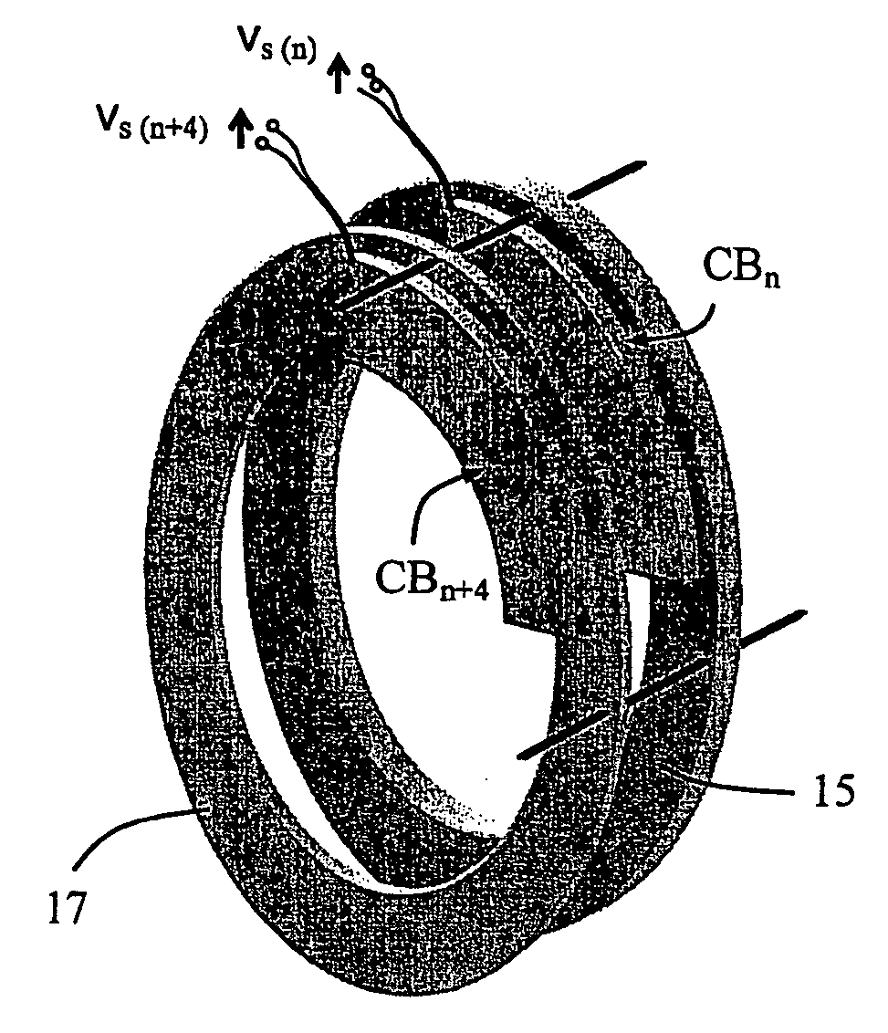
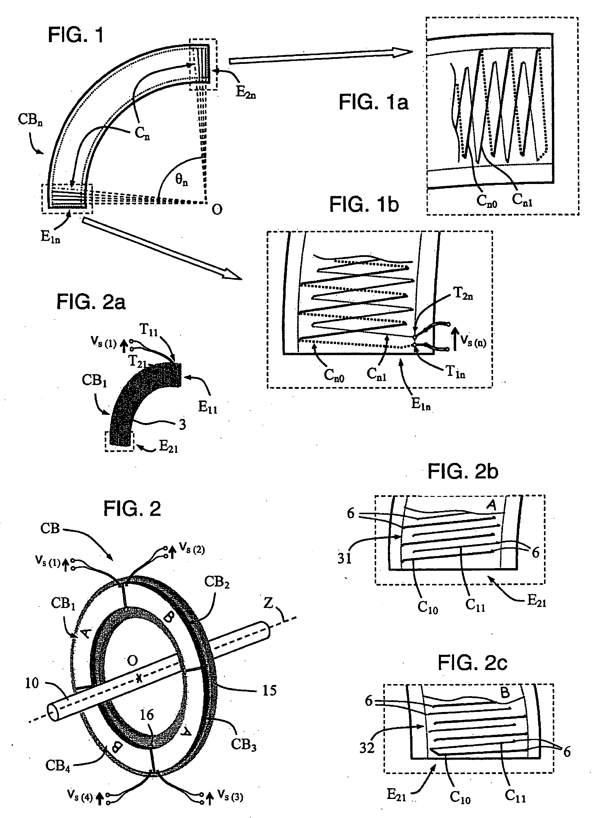
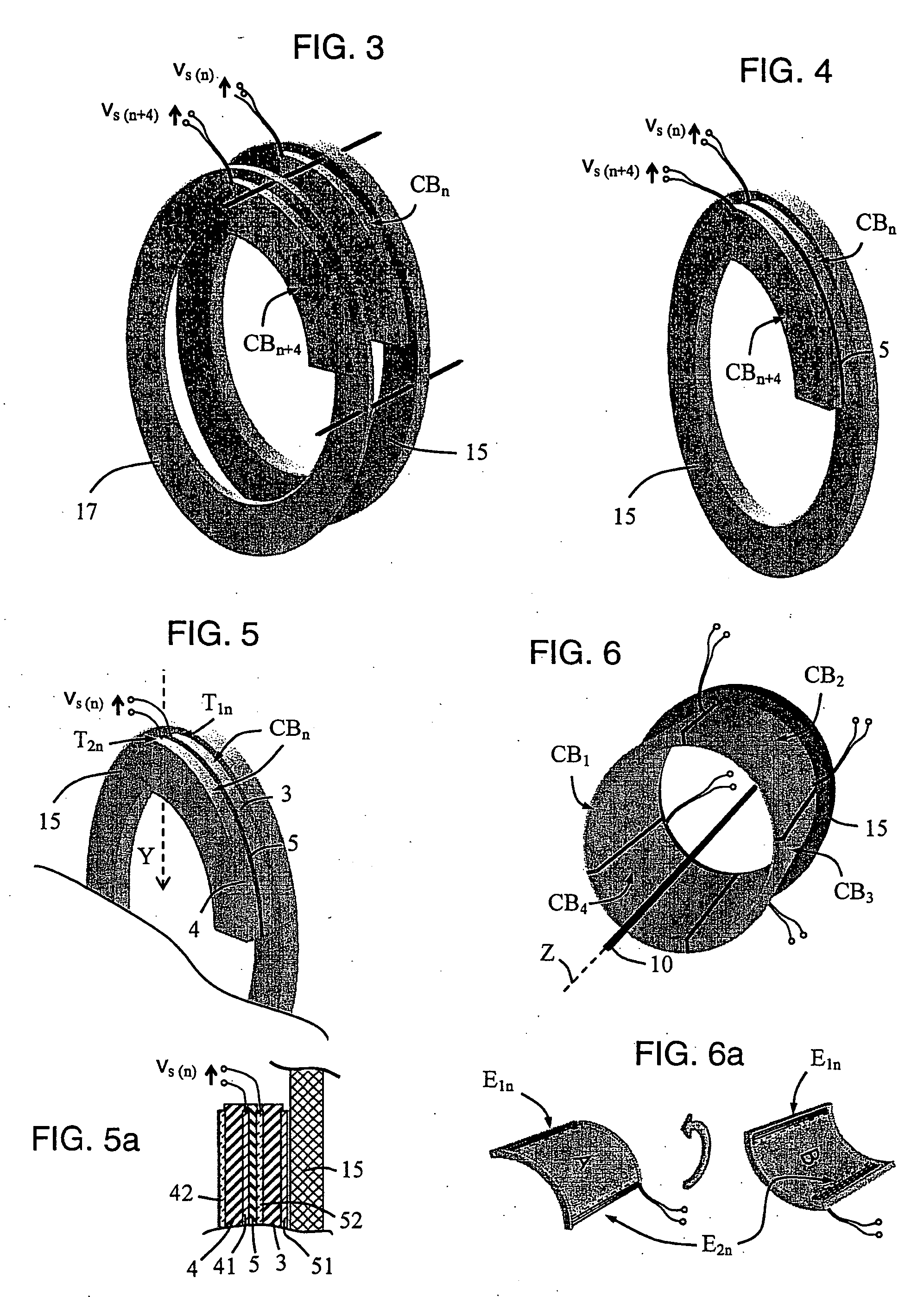
[0042] In FIG. 1, a partial circuit CBn for a current transformer of the invention is shown diagrammatically in the form of a plane annular quarter made using pcb technology. The method of making the turns of a pcb Rogowski winding is known from patent document EP 0 573 350, which allows the rectilinear metal tracks that are provided on the two faces of the printed circuit to be disposed on radii which, when extended, pass through the center θ of the annular quarter. The angular extent On of the partial circuit is equal to 90° in this case, such that a complete circuit is formed by associating four identical partial circuits with one another in a common plane in order to constitute the secondary conductor of a Rogowski type transformer. Below, the term “secondary circuit” is used to designate a secondary conductor of a current transformer of the invention, in particular when made using pcb technology. With present-day machines for manufacturing pcbs, it is possible to make a partial...


PUM


Abstract

The current transformer comprises at least two partial circuits (CBn) each comprising a Rogowski type winding (Cn), each of said the partial circuits being made in the form of an angular portion of a complete circuit (CB) which surrounds at least one primary conductor (10, 10A, 10B, 10C) of the transformer over 360°. The winding (Cn) of each partial circuit (CBn) is constituted by a go winding (Cn0) and by a return winding (Cn1) which extend over the angular extent (θn) of the partial circuit (CBn). For each partial circuit (CBn), the go and return windings are electrically connected in series, both having turns wound in the same direction so as to form a single winding (Cn) which presents a pair of adjacent electrical terminations (T1n, T2n) connected to an acquisition system (7, 7′).

Description

TECHNICAL FIELD [0001] The invention relates to a current transformer comprising at least two partial circuits each comprising a Rogowski type winding, each of the partial circuits being made in the form of an angular portion of a complete circuit surrounding the primary conductor of the transformer over 360°. The winding of each partial circuit is constituted by a go winding and by a return winding which occupy the angular extent of the partial circuit. The complete circuit is equivalent to a Rogowski type secondary circuit of the transformer. A voltage signal measured on this secondary circuit is thus proportional to the derivative of the current conveyed by the primary conductor. STATE OF THE PRIOR ART [0002] It is recalled that a Rogowski coil, also referred to as a Rogowski torus, is conventionally in the form of a conductor wound on a former of toroidal shape and made of a material that is not ferromagnetic, thereby giving it excellent characteristics of linearity due to its l...

Claims


Application Information

Patent Timeline
IPC IPC(8): H01F38/28G01R15/18H01F5/00
CPCH01F5/003G01R15/181
Inventor DUPRAZ, JEAN-PIERRELUCOT, LIONELCHUNIAUD, OLIVIERREGNIER, BERNARD
Owner ALSTOM TECH LTD
Why Eureka
Try Eureka