
Event eyeglasses

a technology of eyeglasses and spectacles, applied in the field of eyeglasses, can solve the problems of static information printed on the pen, inability to change, and only having so much space for a company

Inactive Publication Date: 2005-11-10
HOWELL THOMAS A +3
View PDF64 Cites 100 Cited by
  • Summary
  • Abstract
  • Description
  • Claims
  • Application Information

AI Technical Summary

Benefits of technology

[0009] One embodiment of the invention includes a pair of glasses that can provide, in an audio manner, information to a user. The user does not have to hold onto the glasses to hear the information. In other words, the information is provided in a hands-free manner. The information can be pre-recorded. In another embodiment, the information is transmitted to and received by the glasses. This allows the information to be dynamic. Though not necessary, the information can be directly relevant to an event attended by the user. There can also be a user input mechanism at the glasses to allow the user to provide user input, including user feedback.
[0017] In yet another embodiment, the glasses function as a headset, and are wired or wirelessly coupled to a portable device. The portable device can also be carried by the user of the glasses. The portable device can provide more areas for user inputs and outputs.

Problems solved by technology

But, the pen only has so much space for a company to provide information.
Also, the information printed on the pen is static and cannot be changed.

Method used


Image

  • Event eyeglasses
  • Event eyeglasses
  • Event eyeglasses

Examples


embodiment 10

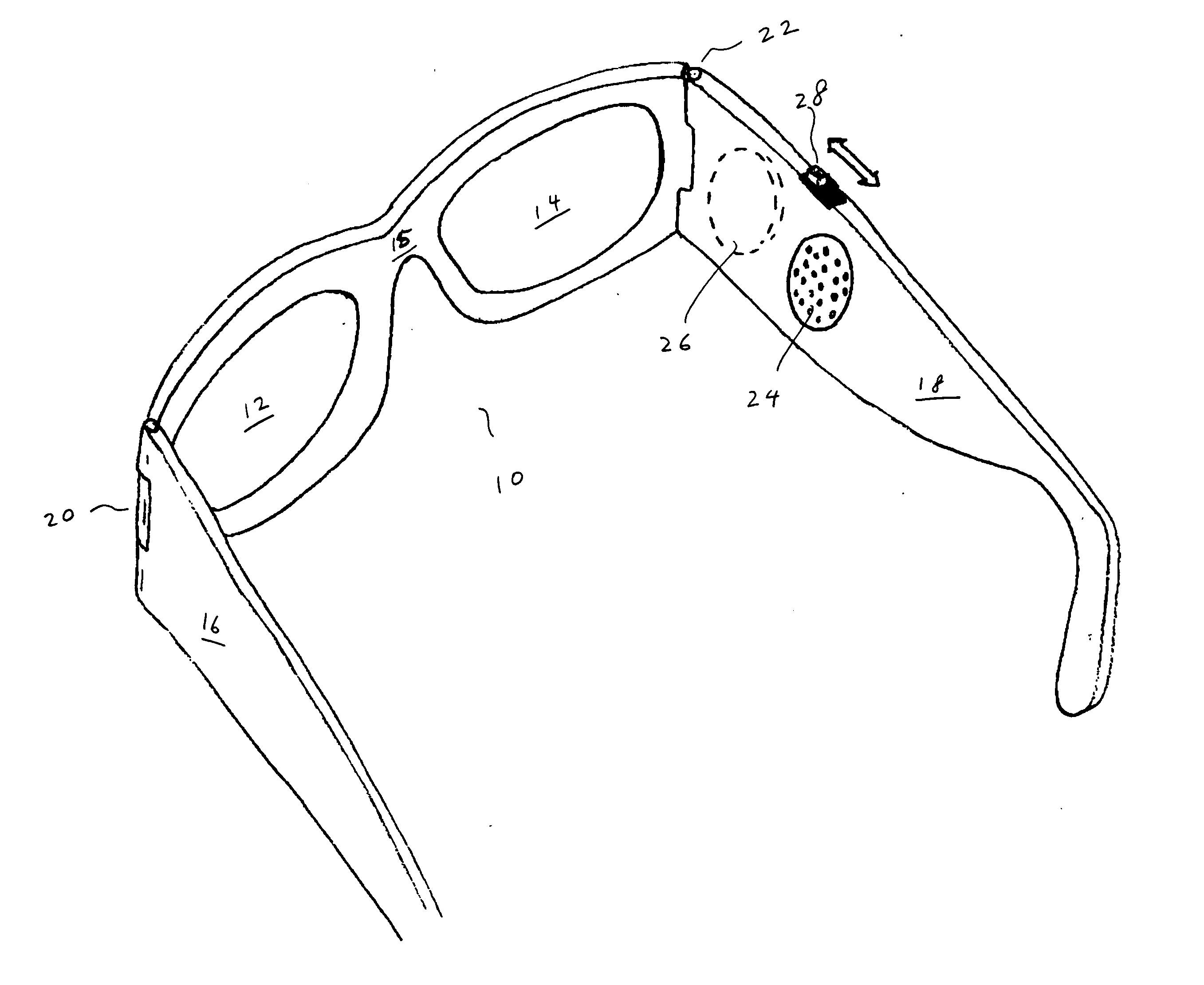
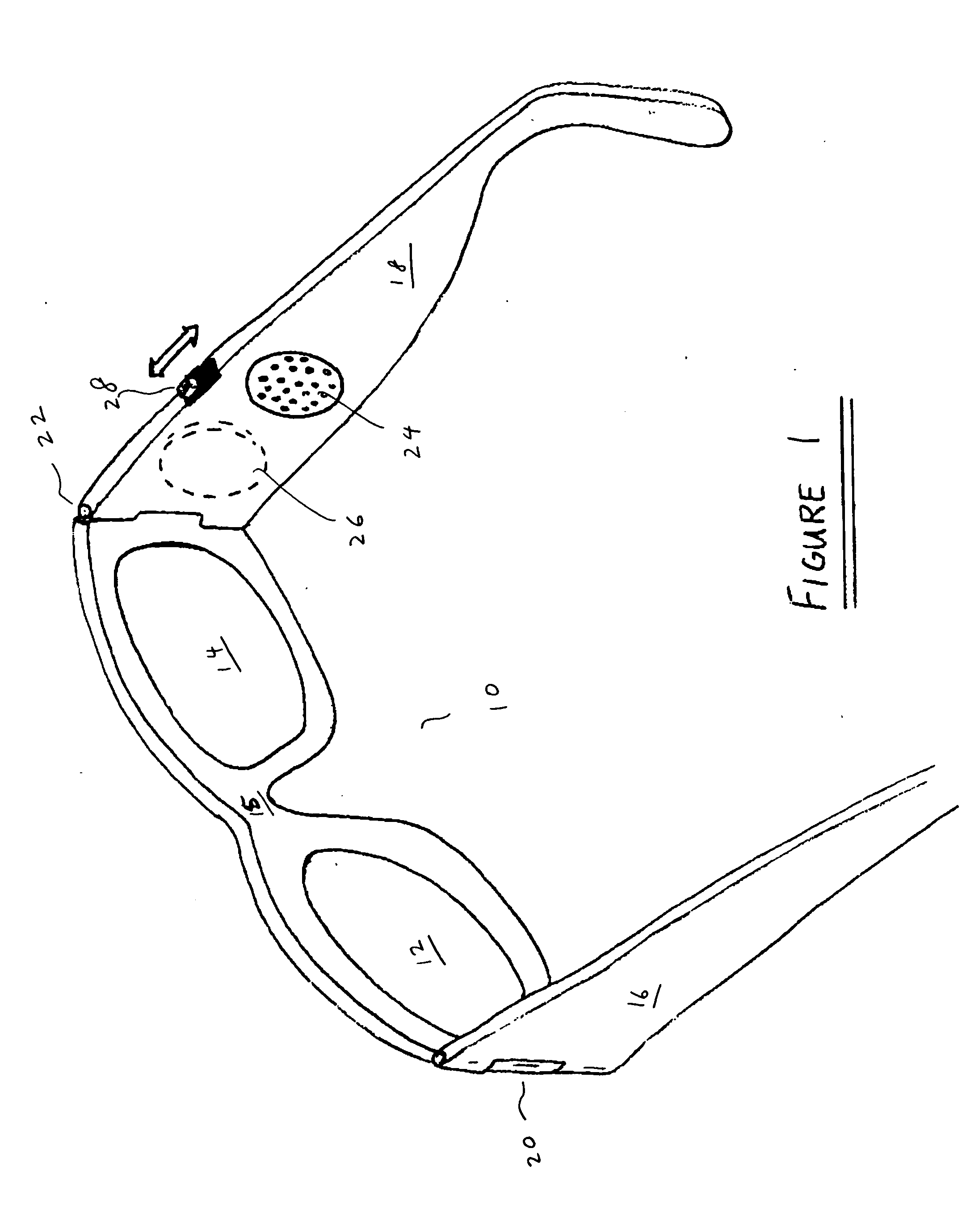
[0049] Referring back to FIG. 1, the embodiment 10 includes a speaker 24 that is at least partially embedded into the glasses. There are different approaches to embed an electrical component, such as a speaker, into different types of glasses. A number of approaches are described, for example, in the various related patent application noted above.

[0050] In one embodiment, the pair of glasses 10 shown in FIG. 1 includes a radio, and the speaker is a part of the radio. All the electronics for the radio are at least partially embedded in the glasses. For example, the electronics can be on a printed circuit board, and the board is in one of the temples of the glasses. Information is provided to the user through the radio. The radio can be an AM or a FM receiver. In one embodiment, the receiver is pretuned to the frequencies of the transmitter of the information. Or, before the glasses are distributed, the radio is set to receive signals from a specific frequency band. Also the radio may...

embodiment 300

[0089]FIG. 7A shows an embodiment 300 with a wheel 302 (roller) having clear strips, 304, 306 and 308, alternating with black strips, 310, 312 and 314, and two photodiodes, 316 and 318. Most of the wheel 302 and the two diodes, after incorporated into the temple 320, are covered by a piece of material 322. The two diodes, 316 and 318, are exposed to ambient light through a clear window 324. A part of the wheel 302 is extended out of the temple 320, allowing the wheel 302 to be turned about its axis 326. The wheel 302 can have teeth for friction turning. As the wheel 302 rotates about the axis 326, based on the differential outputs from the diodes, the direction of movement of the wheel 302—clockwise or counterclockwise—is determined. For example, if the wheel 302 is rotated clockwise, the top diode 316 senses light before the bottom 318 senses light. On the other hand, if the wheel 302 is rotated counterclockwise, the bottom diode 318 senses light before the top 316. Based on the si...

embodiment 350

[0090]FIG. 7B shows an embodiment 350 with a wheel 352 having black 354 and reflecting 356 strips, two photodiodes, 358 and 360, and a LED 362. Again, most of the wheel, the two diodes and the LED are covered by a sheet of material 364. If a reflecting strip 356, instead of a black strip 354, goes over a diode, more light from the LED will be reflected back and received by the diode. If a black strip 354 goes over a diode, output from the diode will be significantly reduced. Again based on the signals from the diodes, the direction of rotation can be determined, which, in turn, can be used to indicate incrementing or decrementing outputs.


PUM


Abstract

A pair of glasses with first and second lens holders for receiving lenses, a bridge element that couples the lens holders, and a pair of temples. The temples are pivotally secured to the lens holders. In one embodiment, the glasses further include a speaker being powered by a power source. The pair of glasses can deliver information through the speaker to the person wearing the glasses. The information being delivered can be wirelessly transmitted to the glasses from a remote device. The information can be pre-recorded and available at the glasses, or the information can be wirelessly received by the glasses as it is produced. The information can be relevant to an event, and available for a relatively short duration of time. In another embodiment, a pair of glasses further includes an information input mechanism that allows the person to input information into the glasses. Such input information can be wirelessly transmitted from the glasses to a remote device.

Description

CROSS-REFERENCE TO RELATED APPLICATIONS [0001] This application is a continuation-in-part of U.S. patent application Ser. No. 10 / 964,011, filed Oct. 12, 2004, and entitled “TETHERED ELECTRICAL COMPONENTS FOR EYEGLASSES,” which is hereby incorporated herein by reference, which in turn claims priority to each of: (i) U.S. Provisional Patent Application No. 60 / 509,631, filed Oct. 9, 2003, and entitled “TETHERED ELECTRICAL COMPONENTS FOR EYEGLASSES,” which is hereby incorporated herein by reference; (ii) U.S. Provisional Patent Application No. 60 / 527,565, filed Dec. 8, 2003, and entitled “ADAPTABLE COMMUNICATION TECHNIQUES FOR ELECTRONIC DEVICES,” which is hereby incorporated herein by reference; (iii) U.S. Provisional Patent Application No. 60 / 562,798, filed Apr. 15, 2004, entitled “EYEWEAR WITH ULTRAVIOLET DETECTION SYSTEM,” and which is hereby incorporated herein by reference; (iv) U.S. Provisional Patent Application No. 60 / 583,169, filed Jun. 26, 2004, entitled “ELECTRICAL COMPONENT...

Claims


Application Information

Patent Timeline
IPC IPC(8): G02C1/00G02C5/00G02C5/14G02C7/10G02C11/00G02C11/06
CPCG02C11/10G02C5/001G02C2200/02
Inventor HOWELL, THOMAS A.CHAO, DAVIDTHOMAS, C. DOUGLASSTONG, PETER P.
Owner HOWELL THOMAS A
Learn More