Spring-barrel arrangement for a timepiece

a technology of spring barrel and timepiece, which is applied in the direction of clock driving mechanism, instruments, horology, etc., can solve the problems of barrel core deviating affecting the accuracy of movement or clockwork mechanism, and the spring barrel in the depression can tilt and jam to a considerable extent, so as to achieve the effect of precise mounting of the barrel core and high accuracy of the wheel train of the timepi

Active Publication Date: 2005-11-10
LANGE UHREN
View PDF4 Cites 16 Cited by
  • Summary
  • Abstract
  • Description
  • Claims
  • Application Information

AI Technical Summary

Benefits of technology

[0007] An object of the present invention is to provide a spring-barrel arrangement for a timepiece which, along with high accuracy of the wheel train of the timepiece, is distinguished by requiring only a small amount of space and allows precise mounting of the barrel core as it runs down.

Problems solved by technology

Since the spring barrel is only mounted in the small step of the depression, the bearing length in relation to the diameter of the spring barrel is small, with the result that the spring barrel in the depression can tilt and jam to a considerable extent in deviation from its desired axis.
Mounting the barrel core independently of the spring barrel also results in the barrel core deviating to a considerable extent from the desired axis, which, via the first wheel of the wheel train which is connected to the barrel core, adversely affects the accuracy of the movement or clockwork mechanism.

Method used


Image

  • Spring-barrel arrangement for a timepiece
  • Spring-barrel arrangement for a timepiece
  • Spring-barrel arrangement for a timepiece

Examples


Embodiment Construction

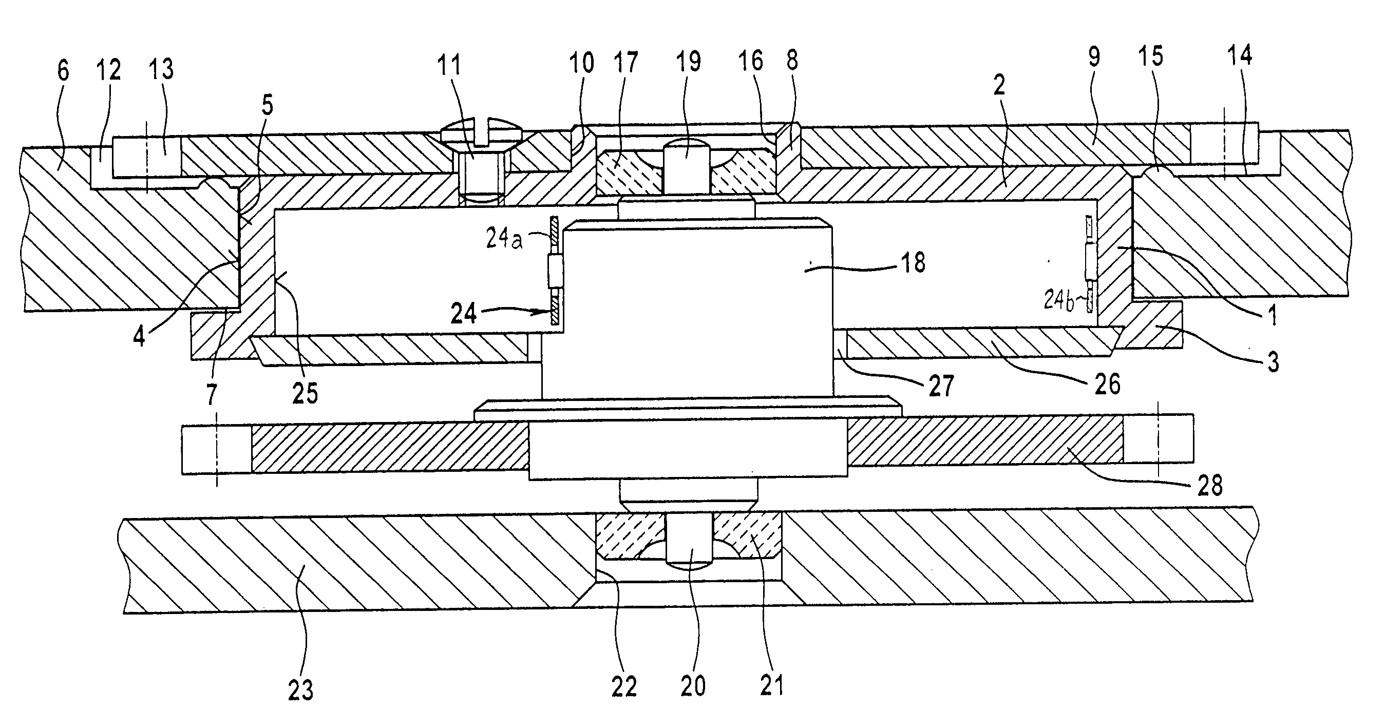
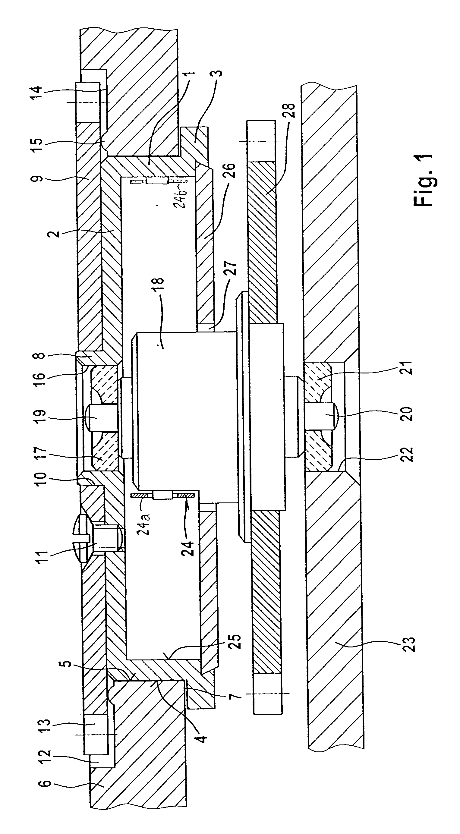
[0041] The spring-barrel arrangements illustrated in FIGS. 1 and 2 have a cup-shaped spring barrel 1 with a base 2. A first, annular supporting region 3 which widens in a flange-like manner is arranged at a cup opening of the cup-like spring barrel 1.

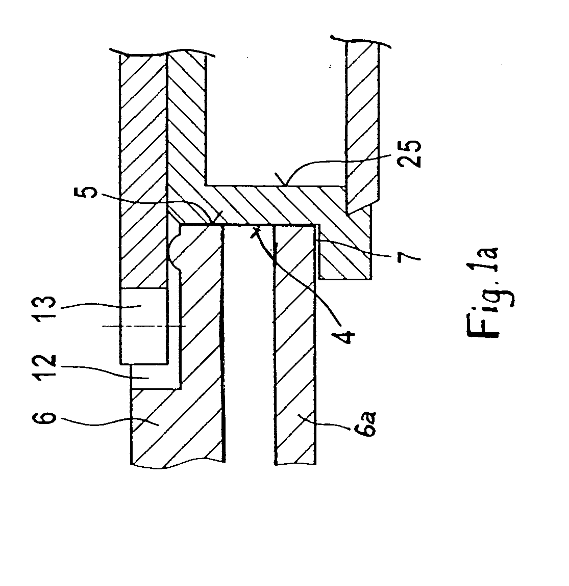
[0042] The spring barrel 1 has a cylindrical outer contour 4 which is inserted into a circular cutout 5 in a wheel bridge 6, until the supporting region 3 butts against one side surface 7 of the wheel bridge 6. The spring barrel is thus rotatably mounted in the wheel bridge 6.

[0043] The axial side of the base 2 of the spring barrel 1 opposing the cup opening has a cylindrical centering extension 8 which projects coaxially towards the outside. A disc-like crown wheel 9 has a central bore 10 corresponding to the centering extension 8 and is fixed to the spring barrel 1 by screws 11.

[0044] The crown wheel 9 extends radially beyond the external diameter of the spring barrel 1 into a stepped recess 12 of the cutout 5, which is designed as...


PUM


Abstract

A spring-barrel arrangement for a timepiece includes a fixed plate-like component with a circular cutout. A spring barrel is rotatably mounted in said circular cutout by its corresponding circular outer contour. A barrel core is coaxially rotatably mounted relatice to the spring barrel and is enclosed by a helical tension spring. An inner end of the spring is connected to the barrel core and its outer end connected to the spring barrel. A crown wheel with a toothed ring is fixed to the spring barrel and a first wheel of a wheel train of the timepiece is fixed to the barrel core. The circular cutout is formed through the plate-like component and the spring barrel has two supporting regions which extend radially beyond the diameter of the circular cutout and are each in abutment against one of the mutually opposite side surfaces of the plate-like component.

Description

BACKGROUND OF THE INVENTION [0001] 1. Field of the Invention [0002] The present invention relates to a spring-barrel arrangement for a timepiece, including a fixed plate-like component which has a circular cutout in which a spring barrel is rotatably mounted by its corresponding circular outer contour, a barrel core which is rotatable coaxially in relation to the spring barrel, a helical tension spring having an inner end connected to the barrel core and an outer end connected to the spring barrel, a crown wheel having a toothed ring being fixed to the spring barrel, and a first wheel of a wheel train of the timepiece being fixed to the barrel core. [0003] 2. Description of the Related Art [0004] In a known spring-barrel arrangement, an annular spring barrel is mounted in a cup-shaped depression of a plate-like component. A crown wheel, which is fixed to the annular spring barrel, projects into a large step of the depression. An annular part is connected to the plate-like component ...

Claims


Application Information

Patent Timeline
Patent Type & Authority Applications(United States)
IPC IPC(8): G04B1/12G04B1/16G04B1/20G04B29/02G04B33/12
CPCG04B1/12G04B1/16G04B33/12G04B29/02G04B1/20
Inventor SCHNEIDER, JENS
Owner LANGE UHREN
Why Eureka
Try Eureka