
Information processing device and method, program, and recording medium

a technology of information processing device and program, applied in the field of information processing device and method, program and recording medium, can solve the problem of extremely large size of additional buffer

Active Publication Date: 2005-11-10
SONY CORP
View PDF9 Cites 6 Cited by
  • Summary
  • Abstract
  • Description
  • Claims
  • Application Information

AI Technical Summary

Benefits of technology

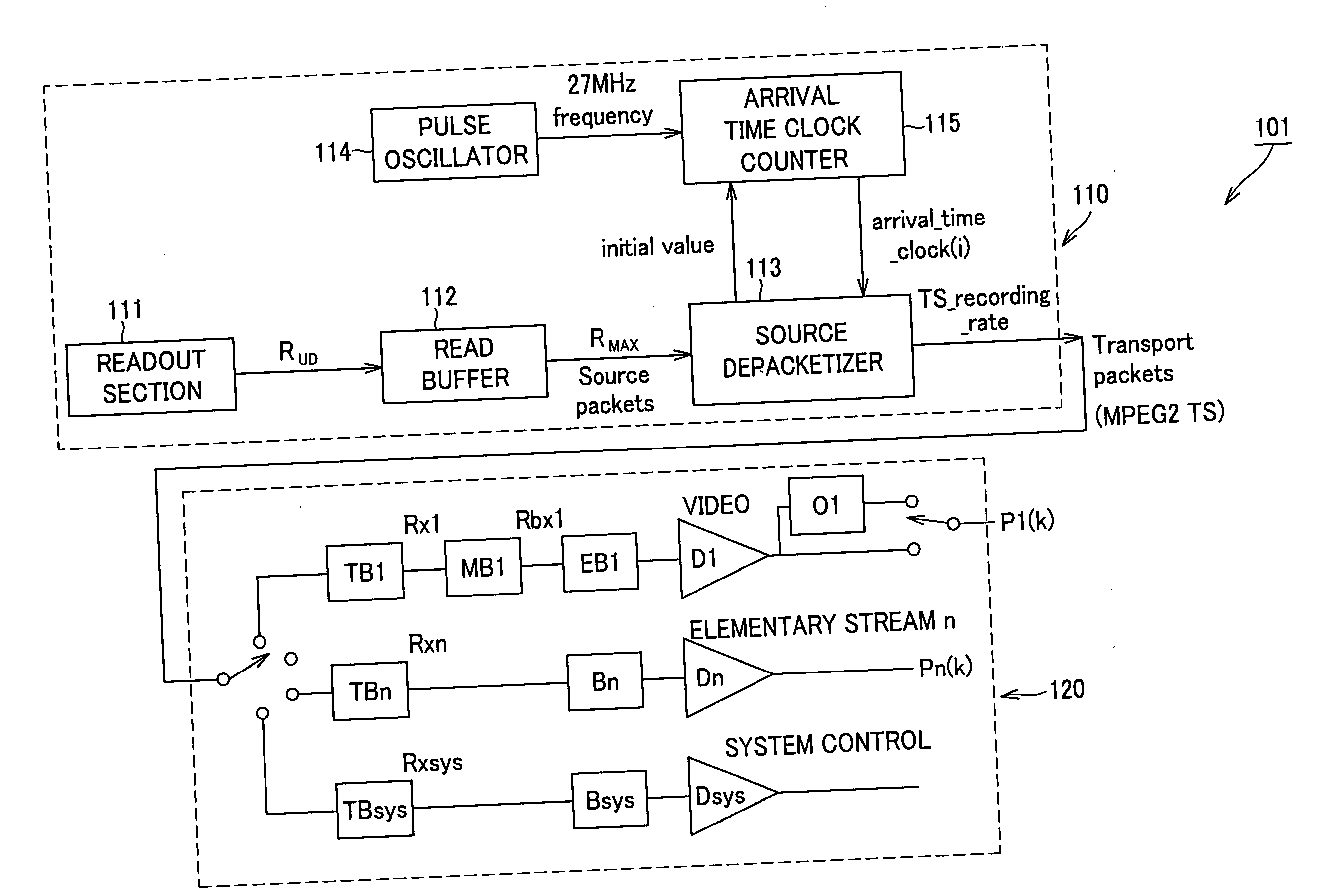
[0051] In the present invention, the audio buffer has a capacity capable of buffering the audio data corresponding to the time required for inputting the second picture to the video buffer, and the source packet is input to the buffer according to arrival_time_stamp of the source packet in the multiplexed stream even between the time at which the input of the first picture to the video buffer is completed and the time at which the input of the last source packet of the first multiplexed stream is completed. This eliminates the additional buffer corresponding to 1 second that has been conventionally required for inputting the transport packet at the maximum bit rate of TS with arrival_time_stamp of the source packet ignored. Further, it is possible to input the picture to be decoded first in the second multiplexed stream to the video buffer by the decoding timing thereof after the last transport packet of the first multiplexed stream has been input.
[0053] It is preferable that the audio buffer has a capacity capable of buffering the audio data corresponding to 100 milliseconds. Since the data amount of I picture according to MPEG2 specification is 10% or less of the data amount transmitted in 1 second in general, it is possible to input I picture to the video buffer by the decode timing thereof by setting the capacity of the audio buffer to the size corresponding to 100 milliseconds to allow the audio buffer to move ahead the audio data by that amount. As a result, encoding restriction on video data is reduced. That is, by setting the capacity of the audio buffer to the above size, it is possible to form a multiplexed stream so that the input of the audio data is completed 100 milliseconds earlier than the reproduction timing thereof.
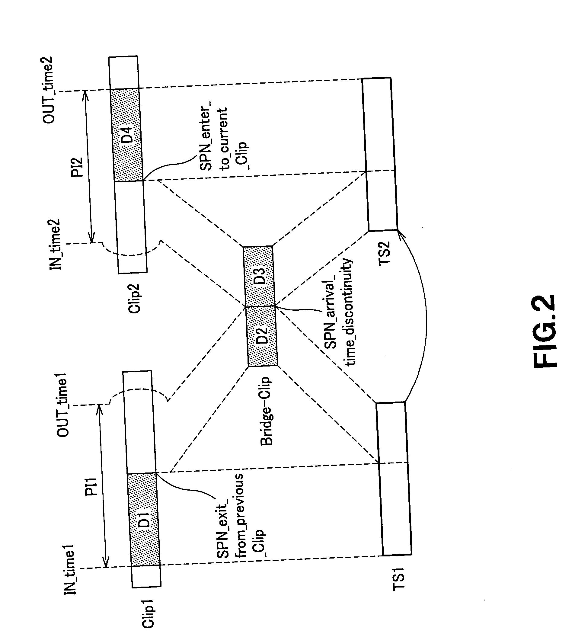
[0055] Further, it is preferable to configure the information processing device such that after a lapse of a predetermined time delta1 after the last source packet of the first multiplexed stream has been output from the output means, the first source packet of the second multiplexed stream is output from the output means. In this case, STC22start>STC21end is satisfied. As a result, determination of the input timing of the first source packet of the second multiplexed stream becomes more flexible, which makes it easy to encode the second multiplexed stream.
[0056] Further, assuming that STC_delta is a time difference between presentation end time of the first picture on the time axis of the first multiplexed stream and presentation start time of the second picture on the time axis of the second multiplexed stream, it is possible to configure the information processing device such that after a lapse of a predetermined time ATC_delta after the output of the last source packet of the first multiplexed stream has been started, the first source packet of the second multiplexed stream is output from the output means, the predetermined time ATC_delta is so determined as to satisfy the time difference STC_delta, and the multiplexed stream is so formed as to satisfy the time difference STC_delta. As a result, determination of the input timing of the first source packet of the second multiplexed stream becomes more flexible, which makes it easy to encode the second multiplexed stream.
[0063] In the present invention, multiplexing are performed such that the input of the audio data corresponding to e.g., 100 milliseconds, which corresponds to the time required for inputting the second picture to the decoder, is completed by the time at which the input of the second picture to the decoder is started. As a result, in the decoder, audio data is moved ahead to the audio buffer to sufficiently assure the time to transmit the second picture, such as I picture, by the decode timing thereof, which makes it easy to encode the multiplexed stream.

Problems solved by technology

Thus, in the case where the above multichannel audio data is employed, the size of the additional buffer becomes extremely large.

Method used


Image

  • Information processing device and method, program, and recording medium
  • Information processing device and method, program, and recording medium
  • Information processing device and method, program, and recording medium

Examples


Embodiment Construction

[0081] An embodiment of the present invention will be described in detail below with reference to the accompanying drawings. This embodiment is obtained by applying the present invention to an information processing device that continuously reproduces, in a seamless manner, two multiplexed AV streams consisting of video and audio streams. The present embodiment will propose an audio buffer that has the optimum capacity available at reproduction of the two AV streams that are seamlessly connected to each other provided in a DVR-STD (Digital Video Recording-System Target Decoder).

[0082] Firstly, the terms used in the following description are defined. “Clip” denotes a multiplexed stream of video and audio streams. “PlayList” denotes a group of reproduction zones in the Clip. One reproduction zone in some Clip is called “PlayItem”, which is represented by a pair of IN point and OUT point on a time axis. That is, PlayList is a group of PlayItem.

[0083]“Reproducing PlayItems in a seamle...


PUM


Abstract

A player model (1) includes an output section (10) that reads out a source packet having a transport packet and arrival time stamp from TS1 and TS2 connected seamlessly to each other and outputs the transport packet according to the arrival time stamp, and a decoder (20) that decodes the transport packet. The output section (10) inputs the transport packet according to the arrival time stamp of the source packet to the decoder (20). The decoder (20) includes an audio buffer TBn having a capacity capable of buffering the audio data corresponding to the time required for inputting I picture, which is the first picture of TS2, to a video buffer TB1.

Description

DESCRIPTION [0001] 1. Technical Field [0002] The present invention relates to an information processing device for editing a multiplexed stream consisting of video and audio streams with video frame accuracy and seamlessly reproducing the edit point, its method, a program, and recording medium and, an information processing device that generates a multiplexed stream in the optimum form for seamless reproduction and a recording medium that stores the multiplexed stream data. [0003] The present application claims priority from Japanese Patent Application No. 2003-130661 filed on May 8, 2003, the content of which is hereby incorporated by reference into this application. [0004] 2. Background Art [0005] A method for editing a multiplexed stream of video and audio streams with video frame accuracy and seamlessly reproducing edit points is described in Jpn. Pat. Appln. Laid-Open Publication No. 2000-175152, Jpn. Pat. Appln. Laid-Open Publication No. 2001-544118, and Jpn. Pat. Appln. Laid-...

Claims


Application Information

Patent Timeline
IPC IPC(8): H04N5/92H04N5/91H04N7/08H04N7/081H04N7/16H04N19/00H04N19/40H04N19/48H04N19/70H04N21/234H04N21/43H04N21/439H04N21/44
CPCH04N21/23406H04N21/23424H04N21/4305H04N21/44016H04N21/4392H04N21/44004H04N21/4307H04N21/43072H04N21/234H04N21/43H04N5/92
Inventor KATO, MOTOKI
Owner SONY CORP
Learn More