System, method and computer program product for controlling image information

a technology of image information and control system, applied in the direction of digital output to print units, instruments, computing, etc., can solve the problems of slow line by line compression, inability to reproduce the boundary between bands with accuracy, and single compression technique may not provide the optimal print quality for all lines of bit map data. achieve the effect of high quality and high speed image formation

Inactive Publication Date: 2005-11-10
RICOH KK
View PDF3 Cites 23 Cited by
  • Summary
  • Abstract
  • Description
  • Claims
  • Application Information

AI Technical Summary

Benefits of technology

[0010] Another object of the present invention is to provide an image information control technique that provides high quality and a high speed image formation.
[0011] Yet another object of the present invention is to provide an image information control technique that allows use of different compression techniques for different portions of a print page.

Problems solved by technology

However, the technology described in patent document JP2001-282482 has a problem in that line by line compression is slow, and a single compression technique may not provide optimum print quality for all lines of the bit map data.
While this band technology provides improved efficiency in compression, a boundary between bands is difficult to reproduce at the printer with accuracy.
This leads to complexity and slow print reproduction, as the overlapping data must be removed by the printer as the printer reproduces the data.
Moreover, as with the technology described above, the use of the same compression technique for all bands of print data may lead to poor quality printing for portions of the page.
While this technique provides improvements in print quality, low compression rates cause slow printing.
Moreover, as with the techniques described above, use of a single compression technique for the entire page of print data may lead to poor quality printing for portions of the page.

Method used


Image

  • System, method and computer program product for controlling image information
  • System, method and computer program product for controlling image information
  • System, method and computer program product for controlling image information

Examples


Embodiment Construction

[0029] Referring now to the drawings, wherein like reference numerals designate identical or corresponding parts throughout the several views, non-limiting embodiments of the present invention are described. In describing preferred embodiments illustrated in the drawings, specific terminology is employed for the sake of clarity. However, the disclosure of this patent specification is not intended to be limited to the specific terminology so selected, and it is to be understood that each specific element includes all technical equivalents that operate in a similar manner.

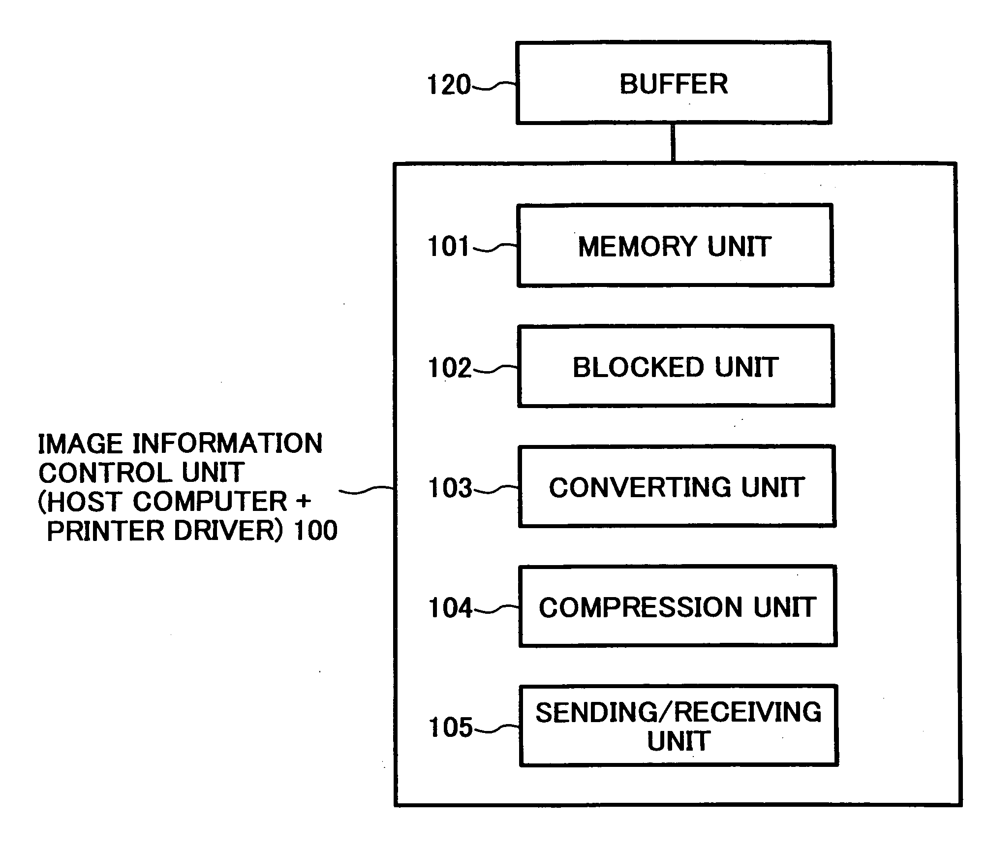
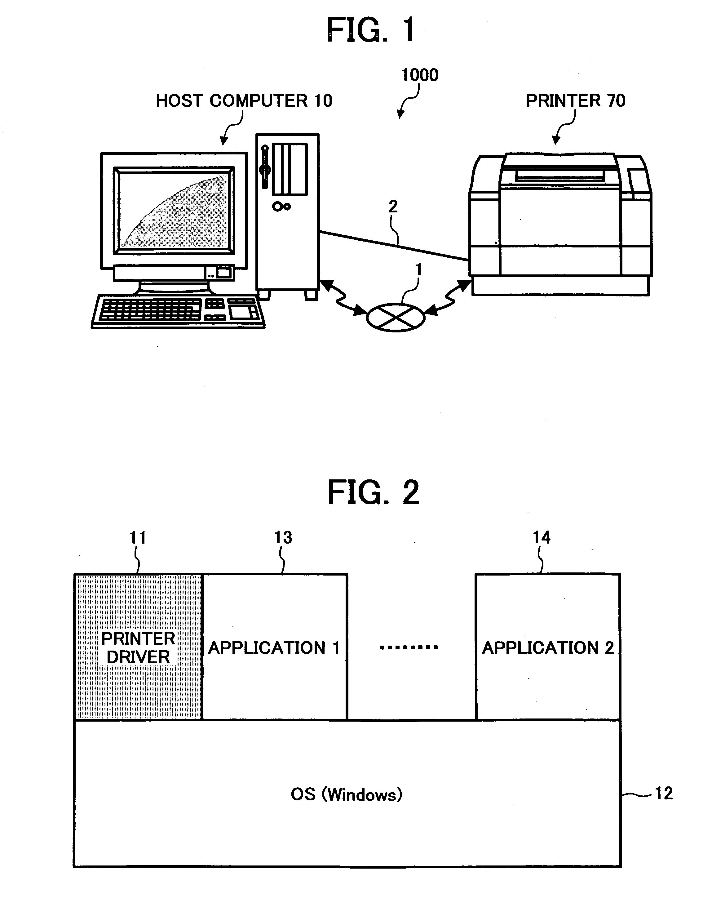
[0030]FIG. 1 shows an exemplary printing system in which embodiments of the present invention may be implemented. As seen in this figure, the print system 1000 includes a host computer 10 and a printer 70. The host computer 10 may be directly connected to the printer 70 by way of at least one of the network connection 1 and a direct connection 3. FIG. 2 is a block diagram of software modules that may be included in ...


PUM


Abstract

An image information control method and apparatus, the apparatus includes a receiving unit configured to receive bit map image data sent from an information process unit, and an accumulating unit configured to accumulate the image data received from the information process unit line by line. A blocked unit is configured to group a plurality of lines of the image data into a predetermined size block of image data. A converting unit is configured to convert the block of image data into a language command corresponding to the image forming apparatus and including the block of image data, and a sending unit is configured to send the language command to the image forming apparatus.

Description

CROSS-REFERENCE TO RELATED APPLICATIONS [0001] This patent document is based on and claims priority to Japanese patent application No. 2004-138996 filed on May 7, 2004 and Japanese patent application 2005-071611 filed Mar. 14, 2005. The entire content of these documents is hereby incorporated herein by reference. BACKGROUND OF THE INVENTION [0002] 1. Field of the Invention [0003] The present invention generally relates to controlling image information and more particularly relates to an image information control apparatus, an image information control system, a printer driver, an image information method, a computer program using the method, and a recording medium for converting data from an application program to a printer command corresponding to an image forming apparatus. [0004] 2. Description of the Background Art [0005] A printer system generally includes a host computer and a printer device connected to the host computer. A printer driver is typically included in the host com...

Claims


Application Information

Patent Timeline
Patent Type & Authority Applications(United States)
IPC IPC(8): G06F3/12G06K9/36
CPCH04N1/6058
Inventor TAKAHASHI, MASATO
Owner RICOH KK
Why Eureka
Try Eureka