Blade shape creation program and method

a technology of blade shape and creation method, which is applied in the direction of piston pumps, vessel construction, instruments, etc., can solve the problems of difficulty in changing each design factor independently, changing each design factor, and difficulty in changing the leading edge side and trailing edge side of the camber lin

Inactive Publication Date: 2005-11-10
MITSUBISHI FUSO TRUCK AND BUS CORPORATION
View PDF6 Cites 19 Cited by
  • Summary
  • Abstract
  • Description
  • Claims
  • Application Information

AI Technical Summary

Problems solved by technology

However, conventional methods, such as the method using “Joukowski airfoil”, pose difficulty in changing each design factor independently.
Needless to say, changing each design factor, independently on the leading edge side and the trailing edge side of the camber line, is also difficult.

Method used


Image

  • Blade shape creation program and method
  • Blade shape creation program and method
  • Blade shape creation program and method

Examples


Embodiment Construction

[0027] Embodiments of the present invention will now be described in detail with reference to the accompanying drawings. The application of a blade shape creation program according to the present invention to the creation of the blade shape of a cooling fan will be taken as an example for explanation.

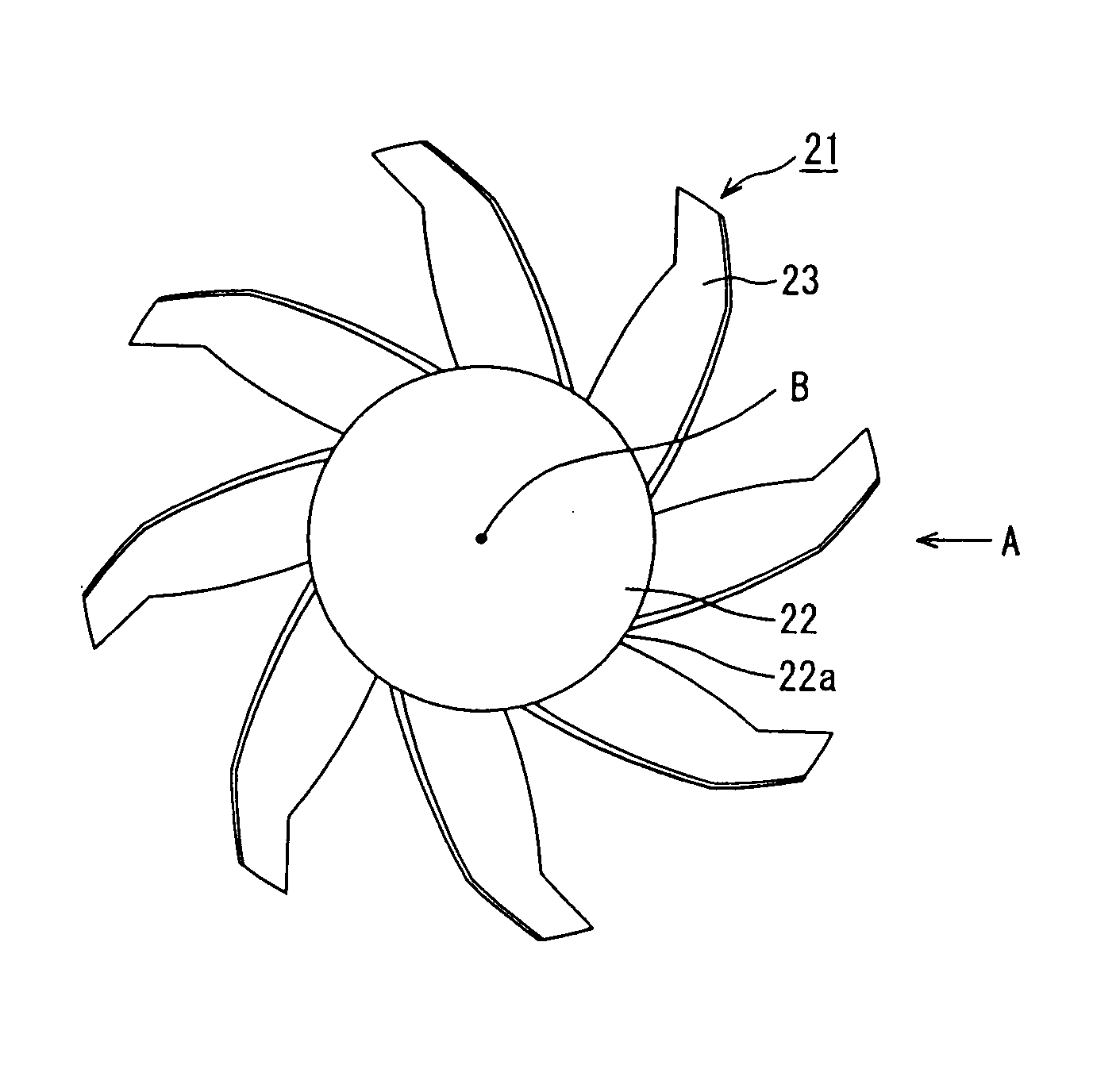
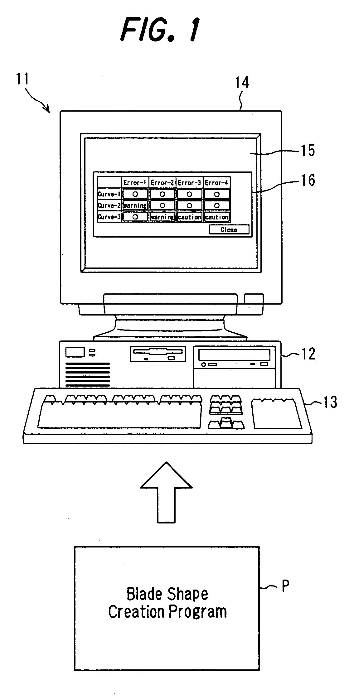
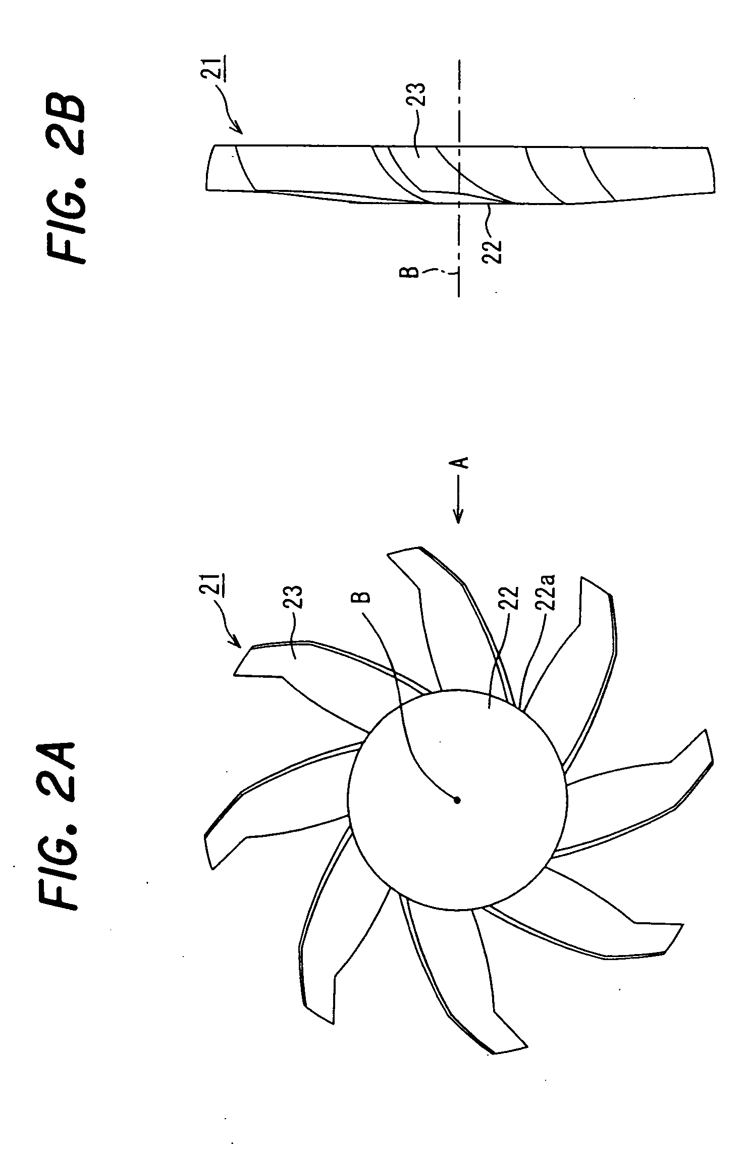
[0028]FIG. 1 is an external outline view of a personal computer for executing a blade shape creation program according to an embodiment of the present invention. FIG. 2A is a front view of a cooling fan, and FIG. 2B is a side view of the cooling fan (a view taken in the direction of A in FIG. 2A).

[0029] As shown in FIG. 1, a personal computer 11 has a computer body 12, and peripheral instruments connected to the computer body 12, such as a keyboard 13 as an input means, and a display device 14 as a display means, for example, a CRT or a liquid crystal display.

[0030] The computer body 12 is equipped with a CPU, a hard disk (HD) drive, and a compact disk (CD) drive, and the CPU execute...


PUM


Abstract

In a blade shape creation program and method, a camber line defining equation for defining a camber line to be defined on a cross section of a blade shape is constructed by a cubic function as a first function defining a leading edge camber line on a leading edge side of a maximum camber point on the camber line, and a cubic function as a second function defining a trailing edge camber line on a trailing edge side of the maximum camber point on the camber line; is defined, with a chord length, a position of maximum camber, a maximum camber value, an inflow angle, and a discharge angle of the camber line being taken as design factors; and has the boundary condition that the first function and the second function have tangents continuous with each other at the maximum camber point.

Description

CROSS REFERENCE TO RELATED APPLICATION [0001] The entire disclosure of Japanese Patent Application No. 2004-099029 filed on Mar. 30, 2004, including specification, claims, drawings and summary, is incorporated herein by reference in its entirety. BACKGROUND OF THE INVENTION [0002] 1. Field of the Invention [0003] This invention relates to a blade shape creation program and method for creating the blade shape of a cooling fan. [0004] 2. Description of the Related Art [0005] When the blade shape of a cooling fan installed in a vehicle is to be created (drawn) in designing the cooling fan, for example, the first step is to create (draw) the cross-sectional shapes of a blade at a plurality of locations in the hub diameter direction of the blade. Then, based on these cross-sectional shapes of the blade, the entire shape of the blade (visible outline and exterior surface) is created (drawn) by spline interpolation or the like. In drawing the cross-sectional shape of the blade, “average ca...

Claims


Application Information

Patent Timeline
Patent Type & Authority Applications(United States)
IPC IPC(8): F04D29/38B63B9/00B63H1/16
CPCB63B9/002B63B71/10
Inventor KAKISHITA, NAOYAKORI, ITSUHEI
Owner MITSUBISHI FUSO TRUCK AND BUS CORPORATION
Why Eureka
Try Eureka