
Multi-carrier communications methods and apparatus

a communication method and multi-carrier technology, applied in the field of communication systems, can solve the problems of relatively high system hardware cost, high cost of communication system deployment, and high cost of wireless bandwidth, so as to improve system performance and robustness, and reduce interference

Active Publication Date: 2005-11-10
QUALCOMM INC
View PDF38 Cites 73 Cited by
  • Summary
  • Abstract
  • Description
  • Claims
  • Application Information

AI Technical Summary

Benefits of technology

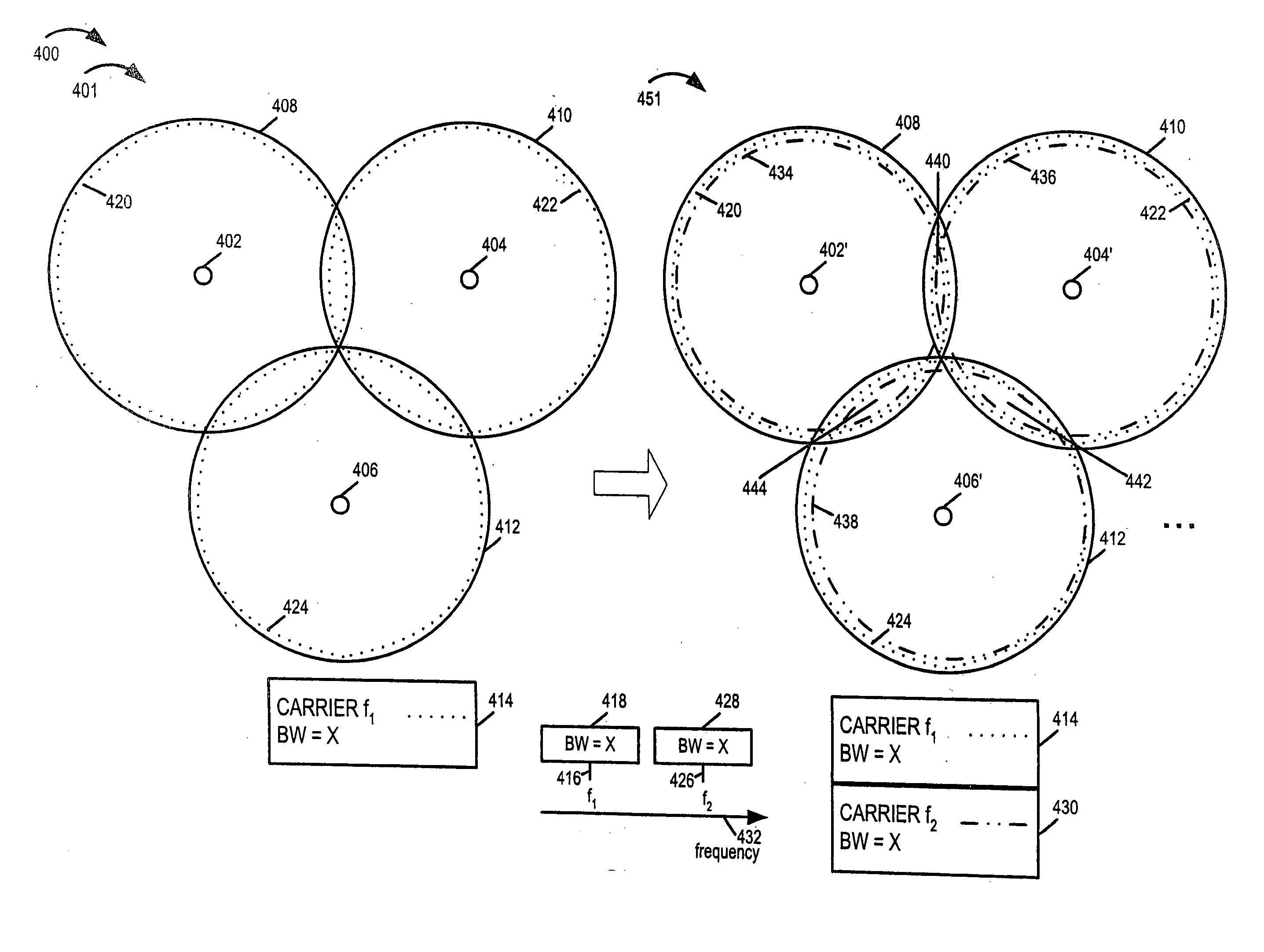
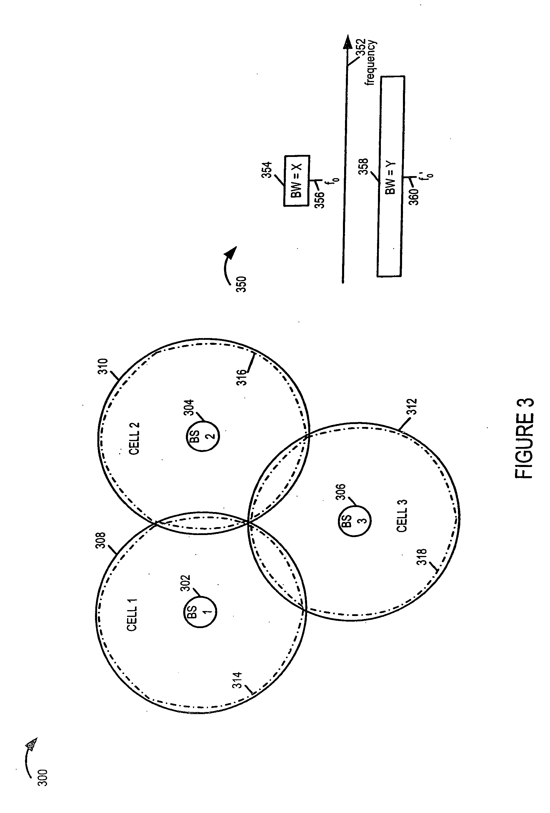
The present invention provides methods and apparatus for deploying a communications system with cells having different configurations to achieve different levels of bandwidth utilization and capacity needs. The invention allows for a gradual deployment of the system, reducing interference between sectors and improving system performance and robustness. The bandwidth can be divided into multiple frequency bands, and different carriers can be assigned different power levels to reduce interference and improve system performance. The invention also allows for the use of different numbers of carriers per sector in different cells and sectors, further improving system performance. The high power signals can be used to transmit cell type information and facilitate mobile node operation in different types of cells.

Problems solved by technology

Deployment of communications systems can be a very costly process.
Wireless bandwidth has become a very expensive commodity.
In addition, system hardware is relatively expensive.
The cost is that all the terminals have to be able to process the signals in the entire wideband channel, thereby increasing the terminal costs and battery power consumption.
The problem of this approach is that when the first carrier is the only carrier used, there could be a significant amount of interference in the first carrier (thus limiting sector throughput), while the other carriers are completely idle.
In addition, changes in the number of carriers and / or carrier frequencies in a cell over time can create problems for older WTs which were not intended to operate on the newly deployed carrier frequencies or do not know the availability of newly deployed carrier frequencies.
This has, in many cases, made the initial deployment of wireless communications systems relatively expensive and / or often inefficient in terms of initial bandwidth utilization.
Deployment and bandwidth under utilization problems tend to be associated with wireless communications systems regards of the particular communications method employed in the system.

Method used


Image

  • Multi-carrier communications methods and apparatus
  • Multi-carrier communications methods and apparatus
  • Multi-carrier communications methods and apparatus

Examples


embodiment 42

[0161] In still another exemplary communication system embodiment, referred to as embodiment 42, the exemplary communication system includes a plurality of cells, each cell including three sectors, each of the three sectors using the same set of three different carrier frequencies to transmit signals, the set of three different carrier frequencies including a first carrier frequency, a second carrier frequency and a third carrier frequency, each sector in an individual cell transmitting signals using the first carrier frequency at different average power levels, each sector in the individual cell also transmitting signals using the second carrier frequency at different average power levels, each sector in the individual cell also transmitting signals using the third carrier frequency at different average power levels such that different average power levels are used for each of the first, second and third carriers in each sector of each individual cell, said average power level corr...

embodiment 15

[0174] In one version of method embodiment 15, referred to as method embodiment (16) the method further includes selecting one of the first, second, third, and fourth carrier frequencies and establishing a communications link with the corresponding one of the first, second, third, and fourth network attachment points, as a function of an estimate of the quality of the first, second, third, and fourth communications links. In one version of such an embodiment, at least one of the first and second carrier frequencies is the same as at least one of the third and fourth carrier frequencies.

[0175] In another version of method embodiment (15) said first and second sectors are located in the first cell. In still another embodiment of method embodiment (15) said second sector is located in a second cell which is different from said first cell in which said first sector is located.

[0176] In one particular version of exemplary method embodiment (15) referred to as method embodiment (20) the ...

embodiment 24

[0179] In one version of method embodiment (23), the stored sector type information further includes information indicating the relative power difference at which signals on different carriers are transmitted within the first sector, and the method further includes determining from the received first sector type indicator signal and said stored information the relative power difference used by the corresponding network attachment point to transmit signals corresponding to the first and second carrier frequencies in the first sector. Such an embodiment is referred to as method embodiment (24). In one version of method embodiment 24, the first cell is a multi-sector cell in which different power levels are used by network attachment points in the sector to transmit signals.

[0180] The above embodiments are only intended to be exemplary and the invention is not to be limited solely to the above numbered embodiments.

[0181] While described in the context of an OFDM system, the methods an...


PUM


Abstract

Methods and apparatus for implementing a multi-carrier communications system are described. Various approaches to a phased system deployment and system configurations resulting from different levels of deployment are described. In addition mobile node and methods of operating mobile nodes in communications systems that may have different levels of deployment in different cells are described.

Description

RELATED APPLICATIONS [0001] The present application claims the benefit of U.S. Provisional Patent Application Ser. No. 60 / 562,901 filed on Apr. 15, 2004 and the benefit of U.S. Provisional Patent Application Ser. No. 60 / 619,540, filed Oct. 15, 2004 and is a continuation-in-part application of International Patent Application No. PCT / US2004 / 034988 filed Oct. 15, 2004, which designated the U.S. and is also a continuation-in-part application of International Application No. PCT / US2004 / 034295, filed Oct. 15, 2005 which designated the U.S., the full content of each of the preceding listed patent applications is hereby expressly incorporated by reference.FIELD OF THE INVENTION [0002] The present invention relates to communications systems and, more particularly, to methods and apparatus for supporting the use of different levels of bandwidth utilization using one or more cell configurations. BACKGROUND [0003] Deployment of communications systems can be a very costly process. Wireless band...

Claims


Application Information

Patent Timeline
Patent Type & Authority Applications(United States)
IPC IPC(8): H04L5/02H04W36/28H04L27/26H04W16/00H04W16/02H04W16/24H04W28/18H04W48/12
CPCH04L5/0007H04W16/12H04L5/0037H04L5/0044H04L5/006H04L5/023H04L27/2602H04W16/24H04W24/02H04W48/12H04W92/20H04L5/0053H04L5/0064H04W52/386H04W52/143H04W52/322H04L5/0035
Inventor LAROIA, RAJIVLI, JUNYIRICHARDSON, TOM
Owner QUALCOMM INC
Learn More