
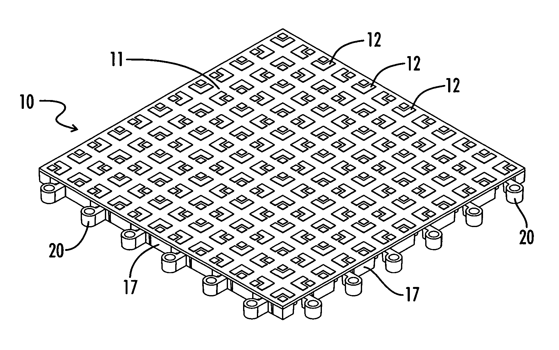
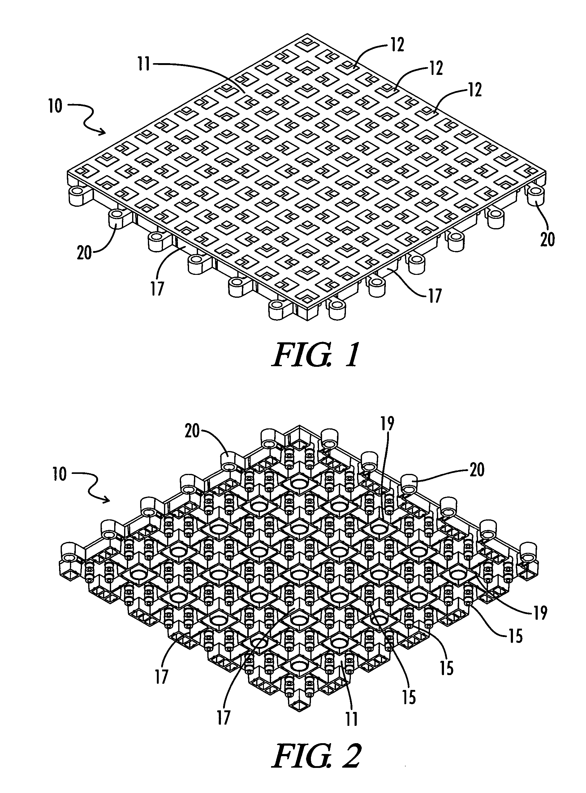
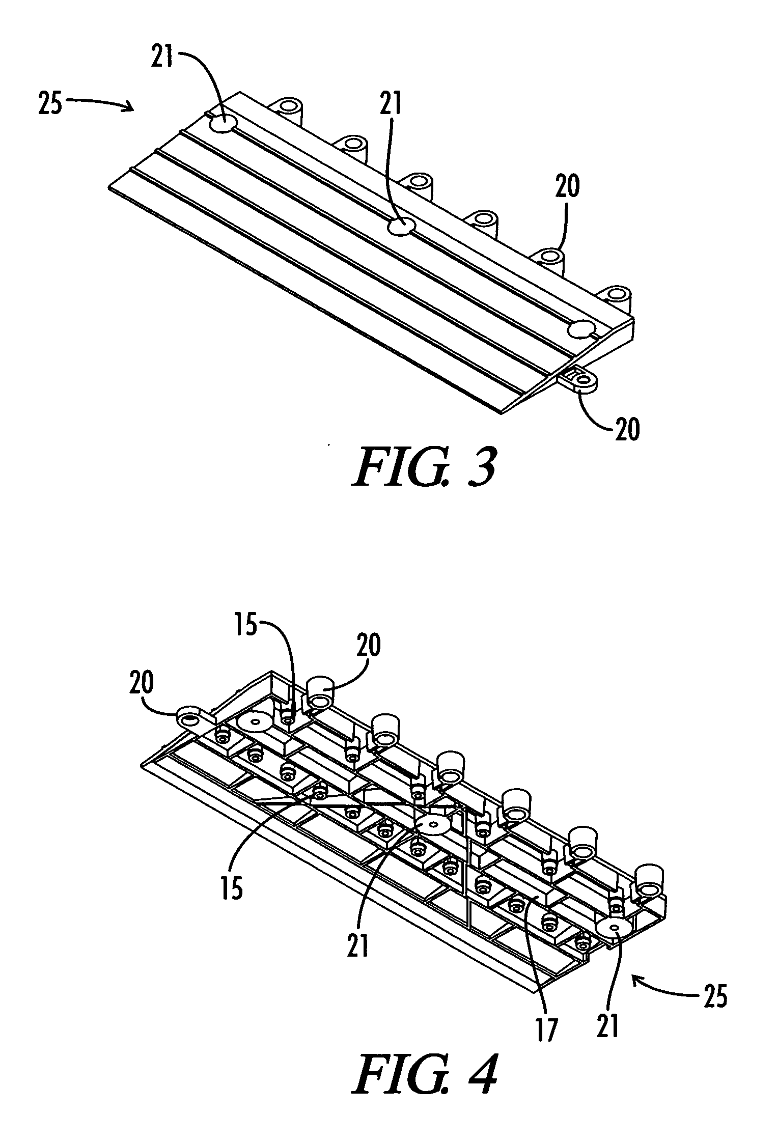
Interlocking modular floor tile

a technology of modular tiles and floor tiles, applied in the field of modular floor tiles and modular floor tiles, can solve the problems of limiting the usefulness of custom sizes, limiting the usefulness of separate connectors, and modular tile systems built with these tiles do not provide a secure fitting, etc., and achieves the effect of convenient modification

Active Publication Date: 2005-11-17
WEARWELL LLC
View PDF28 Cites 93 Cited by
  • Summary
  • Abstract
  • Description
  • Claims
  • Application Information

AI Technical Summary

Benefits of technology

[0016] One object of the present invention is to provide modular floor tile that can easily be modified to cover a floor of any size or shape, but still cooperatively interlock with another tile of the present invention.
[0017] Another object of the present invention is to provide a tile that is easily modified to various sizes, yet interlocks with another tile of the present invention, and provides friction and cushion to a user of the tile.
[0019] Another object of the present invention is to provide a modular tile system that can be adjusted in size, but maintain interlockability with like tiles of the present invention on all sides of the adjusted tile.
[0020] It is a further object of the present invention to provide a modular floor tile that is suitable as a floor covering by absorbing lateral forces and offering traction, but is adjustable in size while maintaining interlockability with like tiles of the present invention.

Problems solved by technology

These separate connectors have not worked well in practice because they get lost or make alignment between adjacent mats difficult during reinstallations after lifting the modular mats out of the system.
The conventional modular floor tiles are not adjustable size-wise, which limit their usefulness with respect to custom sizes.
That is, modular tile systems built with these tiles do not provide a secure fitting if trimmed to adjust size.
Other prior art mats have required separate connectors, which limit their versatility.
These systems have disadvantages because the connectors may get lost or make proper alignment between adjacent mats difficult during installation or reinstallation.

Method used


Image

  • Interlocking modular floor tile
  • Interlocking modular floor tile
  • Interlocking modular floor tile

Examples


Embodiment Construction

[0046] For the purposes of this disclosure, a “mat” or “tile” shall be defined as a covering for the floor or ground. The terms should encompass those covering that have borders around the perimeter edges and also encompass those coverings in which the perimeter has been modified for installation into a recessed area in the floor such as a mat holding well.

[0047] The term “male” refers to pin or peg-type components. The term “female” refers to the components that have a socket or lug-type compartment that is sized and spaced to accommodate the “male” component. The “male” and “female” components are complimentary to one another in the sense that the “male” components may be securely inserted into the “female” components in a way that provides a mechanism for holding adjacent tiles to one another, as well as holding tiles to adjacent border strips (i.e. transition tiles). As described herein, “male” components may be used to assist in providing vertical support to the mat, whether c...


PUM

PropertyMeasurementUnit
lengthaaaaaaaaaa
lengthaaaaaaaaaa
displacement gapaaaaaaaaaa

Abstract

An interlocking, modular floor tile that comprises a planar member defined by a perimeter having four sides and a top surface, a plurality of downwardly projecting support legs of common length dispersed pattern-wise inside the perimeter of the planar member and coupled with the top surface, and at least one female interlocking connector element that extends outside the perimeter of the planar member for receiving a support leg of a like tile and thereby forming an interlock with the like tile.

Description

PRIORITY INFORMATION [0001] This patent application claims priority under 35 U.S.C. § 119(e) of Provisional Patent Application No. 60 / 546,357 filed on Feb. 20, 2004, the contents of which are incorporated herein by reference.FIELD OF THE INVENTION [0002] The present invention relates to the field of modular floor tiles and modular floor tile systems, such as the modular floor tile systems that are installed on an existing floor. The present invention also relates to a connection system for modular floor tiles. The present invention further relates to a free standing modular mat system comprising at least two mats, or tiles. BACKGROUND OF THE INVENTION [0003] Modular floor tiles are often used as components on the construction of a flooring system. The system may be designed as a floor covering for an entire room, or a floor covering for a section if a room. The typical floor system components may be manufactured from, for example, semi-rigid, plasticized, virgin polyvinyl chloride, ...

Claims


Application Information

Patent Timeline
Patent Type & Authority Applications(United States)
IPC IPC(8): E04F15/00E04F15/10
CPCE04F15/10E04F15/02172E01C13/04E04F15/02E04F15/02411
Inventor FUCCELLA, DANIEL C.ALEXANDER, DOUGLAS E.
Owner WEARWELL LLC
Learn More