Method and apparatus for preheating ventilation air for a building

Active Publication Date: 2005-11-17
HOLLICK JOHN
View PDF6 Cites 15 Cited by
  • Summary
  • Abstract
  • Description
  • Claims
  • Application Information

AI Technical Summary

Benefits of technology

[0011] Thus, the air is heated using a two-stage solar heater that provides benefits of both the unglazed and the glazed systems. Advantageously, air is heated to temperatures that are only available using solar collectors with glazing, while the costs are closer to those of the solar collectors without glazing. In one aspect, the unglazed solar collector includes very fine holes that filter much of the dust particles from the air. Thus, air is filtered by first passing the air through the unglazed solar collector, prior to passing the air t

Problems solved by technology

The problem with the conventional approach is that the amount of ventilation air is not controlled, the temperature in the building near the outside walls is lower than average and less comfortable, and additional heat must be provided to heat the outside air to room temperature during the heating season.
During the heating season, the ambient temperature is lower than the room temperature, and therefore a recirculating solar collector operates at a much reduced efficiency level.
While this particular arrangement reduces the need for the use of consumable energy, the use of the glazing increases costs significantly.
The use of a conventional glazed panel suffers other disadvantages including the requirement that the glazed panels be sealed.
This again adds to the cost of the panels.
Alternatively, if the glazed panel

Method used


Image

  • Method and apparatus for preheating ventilation air for a building
  • Method and apparatus for preheating ventilation air for a building
  • Method and apparatus for preheating ventilation air for a building

Examples


Embodiment Construction

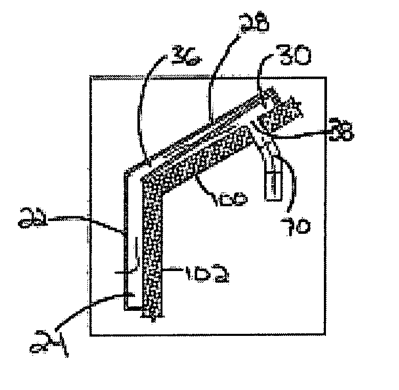
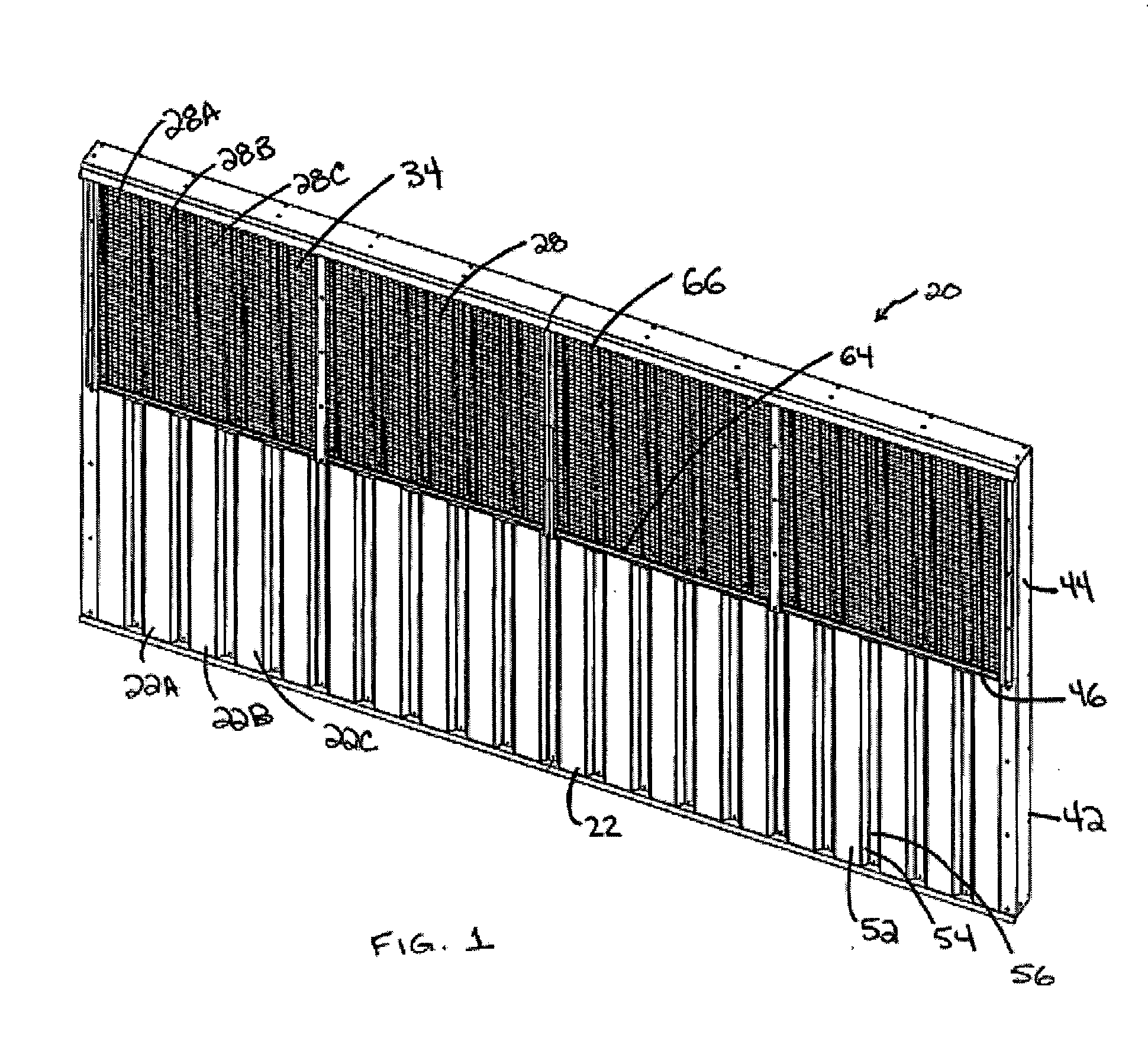
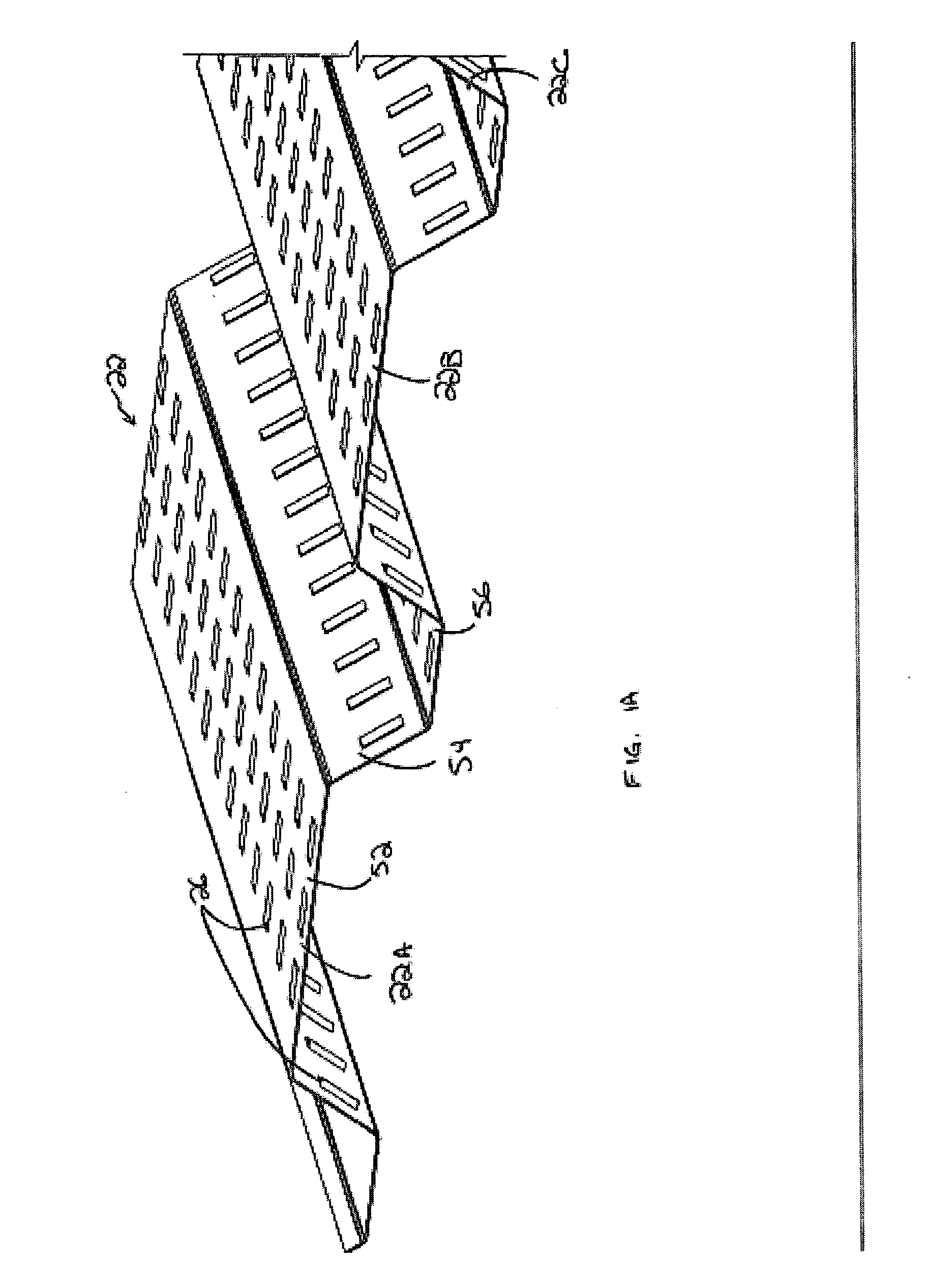
[0023] Reference is first made to FIGS. 1 to 3 to describe a solar heating apparatus for pre-heating ventilation air for a building according an embodiment of the present invention, and indicated generally by the numeral 20. The apparatus 20 includes a first sunlight-absorbent collector panel 22 for locating on the building. The panel 22 is exposed to ambient air and defines a first air collection space 24 between itself and the building. The first sunlight-absorbent collector panel 22 has a plurality of air inlet openings 26 to allow the ambient air to pass through the openings 26 to the first air collection space 24. A second sunlight-absorbent collector panel 28 for locating on the building, adjacent the first sunlight-absorbent collector panel 22, defines a second air collection space 30 between itself and the building. The second sunlight-absorbent collector panel 28 has a plurality of air inlet openings 32 to allow air to pass through the openings 32 to the second air collecti...


PUM


Abstract

An apparatus for pre-heating ventilation air for a building. The apparatus includes a first sunlight-absorbent collector panel on the building. The panel is exposed to ambient air and defines a first air collection space between itself and the building. The first sunlight-absorbent collector panel has a plurality of air inlet openings to allow the ambient air to pass through the openings to the first air collection space. A second sunlight-absorbent collector panel on the building is adjacent the first sunlight-absorbent collector panel and defines a second air collection space between itself and the building. The second sunlight-absorbent collector panel has a plurality of air inlet openings to allow air to pass through the openings to the second air collection space. A glazing covers the second sunlight-absorbent collector panel and defines an intermediary air flow chamber between itself and the second sunlight-absorbent collector panel. The intermediary air flow chamber is in communication with the first air collection space to receive air therefrom. The air inlet openings in the second sunlight-absorbent collector panel provide communication between the intermediary air flow chamber and the second air collection space. An air outlet extends from the second air collection space into the building for air flow therethrough. A fan communicates with the air outlet for moving air from the second air collection space into the building, through the air outlet.

Description

FIELD OF THE INVENTION [0001] The present invention relates in general to the provision of ventilation air for buildings and more particularly, to heating the ventilation air prior to introduction into the building, using solar energy BACKGROUND OF THE INVENTION [0002] Commercial, industrial, domestic and apartment buildings require ventilation, and it is common for the natural leakage around doors, wall-ceiling joints, etc. found in standard building construction to allow sufficient air to enter the building. A pressure drop from the exterior to the interior of the building can arise from many factors, such as high winds, exhaust fans and combustion air for fuel-burning furnaces. This tends to draw outside air into the building through any crack or opening. [0003] The problem with the conventional approach is that the amount of ventilation air is not controlled, the temperature in the building near the outside walls is lower than average and less comfortable, and additional heat mu...

Claims


Application Information

Patent Timeline
IPC IPC(8): F24F5/00F24F7/06F24J2/04F24S10/55F24S10/80
CPCF24F5/0046F24J2/0444F24J2/045Y02E10/44F24J2/28Y02B10/20Y02B10/24F24J2/0488Y02A30/272F24S20/67F24S70/60F24S10/80F24S20/66
Inventor HOLLICK, JOHN
Owner HOLLICK JOHN
Why Eureka
Try Eureka