
Automotive fuel cell siphon/refill tool

Inactive Publication Date: 2005-11-17
FUJIFILM CORP
View PDF5 Cites 21 Cited by
  • Summary
  • Abstract
  • Description
  • Claims
  • Application Information

AI Technical Summary

Benefits of technology

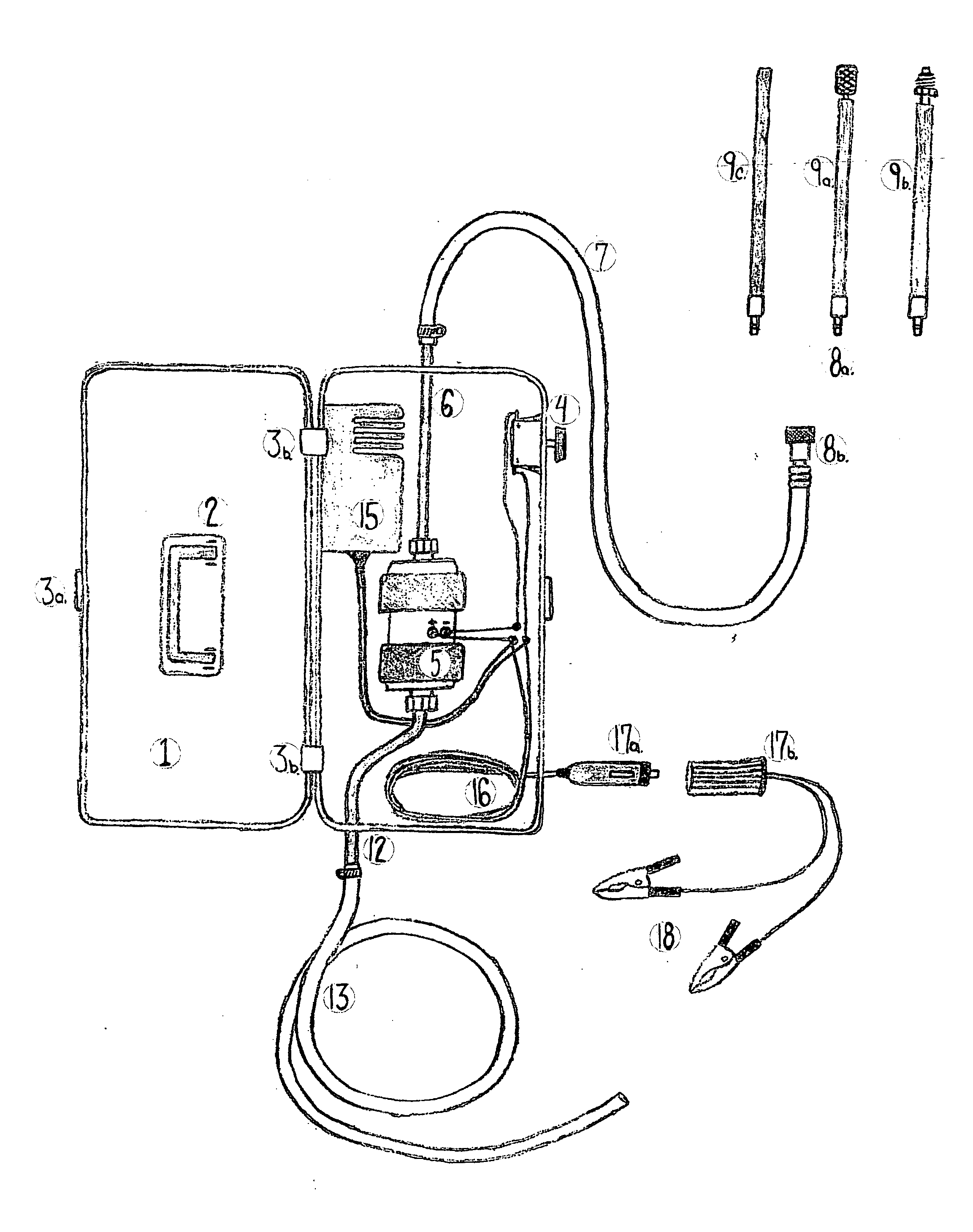
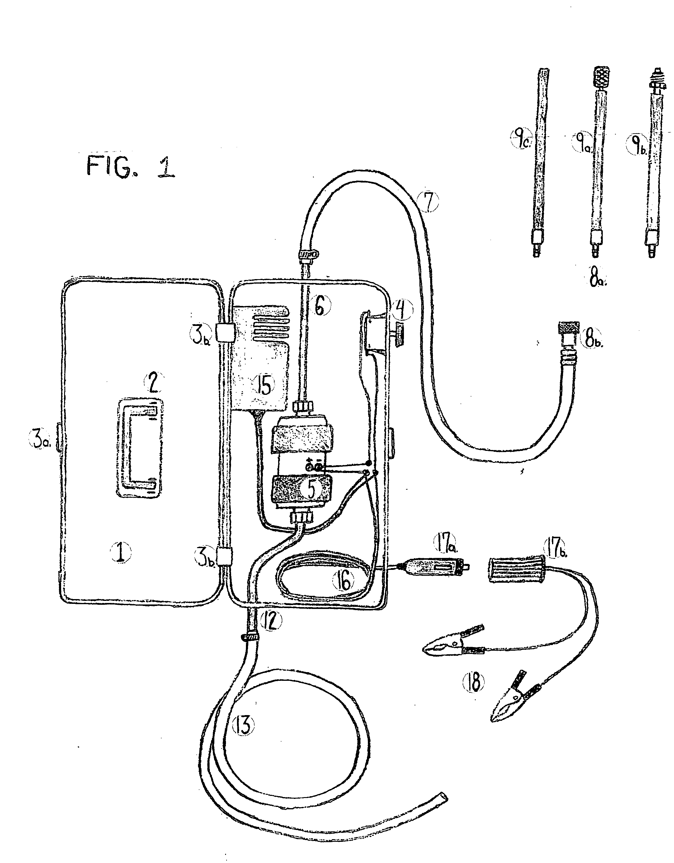
[0013] DISCRIPTION: A handheld case containing a fuel pump, AC and 2 DC electrical hook-ups, outlet hose, inlet hose with quick connect fitting and 3 inlet hose attachments.
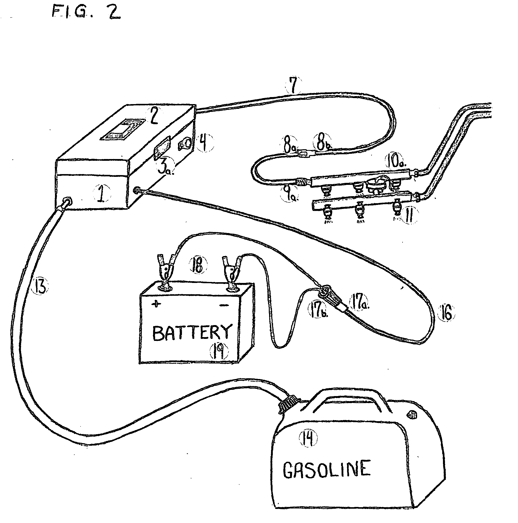
[0014] OPERATION: Connect the applicable fuel removal attachment to the quick connect fitting of the inlet hose of the tool. Fuel may be removed via the fuel filter (2 attachments) or the Schrader Valve located on the fuel rail of all port fuel injec

Problems solved by technology

It is very difficult and unsafe to remove a fuel cell that is full of fuel.

Method used


Image

  • Automotive fuel cell siphon/refill tool
  • Automotive fuel cell siphon/refill tool
  • Automotive fuel cell siphon/refill tool

Examples


Embodiment Construction

[0059] A 6″×12″ plastic box, 4″ deep with a pivoting handle on top for carrying, and a lid that is hinged on the left and a snap clip on the right to keep the lid closed.

[0060] On the inside are an AC / DC power converter, a 12-volt DC electric fuel pump, and a push-button switch. Two wires from the power inverter, positive and negative DC current, connect to the respective polarities of the fuel pump. A push-button switch interrupts the positive wire. A two-wire DC extension cord is spliced in at the respected polarities of the power converter and then exits a hole in the lower right hand side of the box. A steel inlet tube is threaded on to the inlet side of the pump and exits a hole in the top center of the box. A steel outlet tube is threaded on the outlet side of the pump and exits a hole in the bottom center of the box.

[0061] On the outside, the two-blade AC wall plug-in terminals protrude through an oval hole cut in the upper left hand side of the box. The DC extension cord s...


PUM

PropertyMeasurementUnit
Poweraaaaaaaaaa

Abstract

A fuel siphon and refill tool for an automotive fuel cell, containing a DC electric fuel pump, AC / DC power inverter and several attachments. A plastic container housing a fuel pump, power inverter and push-button switch draws fuel from a vehicle fuel cell via the engine fuel rail, or fuel filter connection. The pump then pushes the fuel to an approved container through an open outlet hose. A plurality of sources including an AC extension cord, a cigar lighter receptacle, or a vehicle DC battery powers the pump. The tool may also be used to return fuel to the vehicle by siphoning the fuel from the said approved fuel container, and pushing the fuel into the vehicle fuel cell filler neck.

Description

CROSS-REFERENCE TO RELATED APPLICATIONS [0001] None Applicable STATEMENT REGARDING FEDERALLY SPONSORED RESEARCH OR DEVELOPMENT [0002] Does Not Apply REFERENCE TO SEQUENCE LISTING [0003] Does Not Apply FIELD OF THE INVENTION [0004] The present invention is applied to an automotive fuel cell, specifically one with a fuel filler neck restriction, disallowing a siphon hose to be inserted. BACKGROUND OF THE INVENTION [0005] Late model automotive fuel cells have a safety feature commonly known as a ‘roll-over ball’ located in the fuel filler neck. This is designed to prevent fuel from escaping the cell in the event of a crash that involves the vehicle leaving it's upright position. In doing so, this safety feature prevents fuel removal devices, such as a siphon hose from being inserted into the filler neck far enough to retrieve fuel. [0006] In the event of a failed fuel pump, which is located inside the fuel cell on almost all late model vehicles, an auto technician must remove the vehic...

Claims


Application Information

Patent Timeline
IPC IPC(8): B65B1/04B67D7/04B67D7/62
CPCB67D7/62B67D7/04
Inventor MONTANI, MARK A.
Owner FUJIFILM CORP
Learn More