Drill bit having increased resistance to fatigue cracking and method of producing same

Inactive Publication Date: 2005-11-17
SMITH INT INC
View PDF6 Cites 36 Cited by
  • Summary
  • Abstract
  • Description
  • Claims
  • Application Information

AI Technical Summary

Problems solved by technology

However, although shear bits have been found to drill effectively in softer formations, as the hardness of the formation increases, it has been found that the cutting elements on the shear cutter bits tend to wear and fail, affecting the rate of penetration (ROP) for the shear cutter bit.
A number of different forces can result in early failure of roller cone bits.
These stresses tend to be very high and are cyclical.
As a result, it is common for the cone to crack within some of the sockets.
Cracking in one or more of the sockets can result in loss of

Method used


Image

  • Drill bit having increased resistance to fatigue cracking and method of producing same
  • Drill bit having increased resistance to fatigue cracking and method of producing same
  • Drill bit having increased resistance to fatigue cracking and method of producing same

Examples


Embodiment Construction

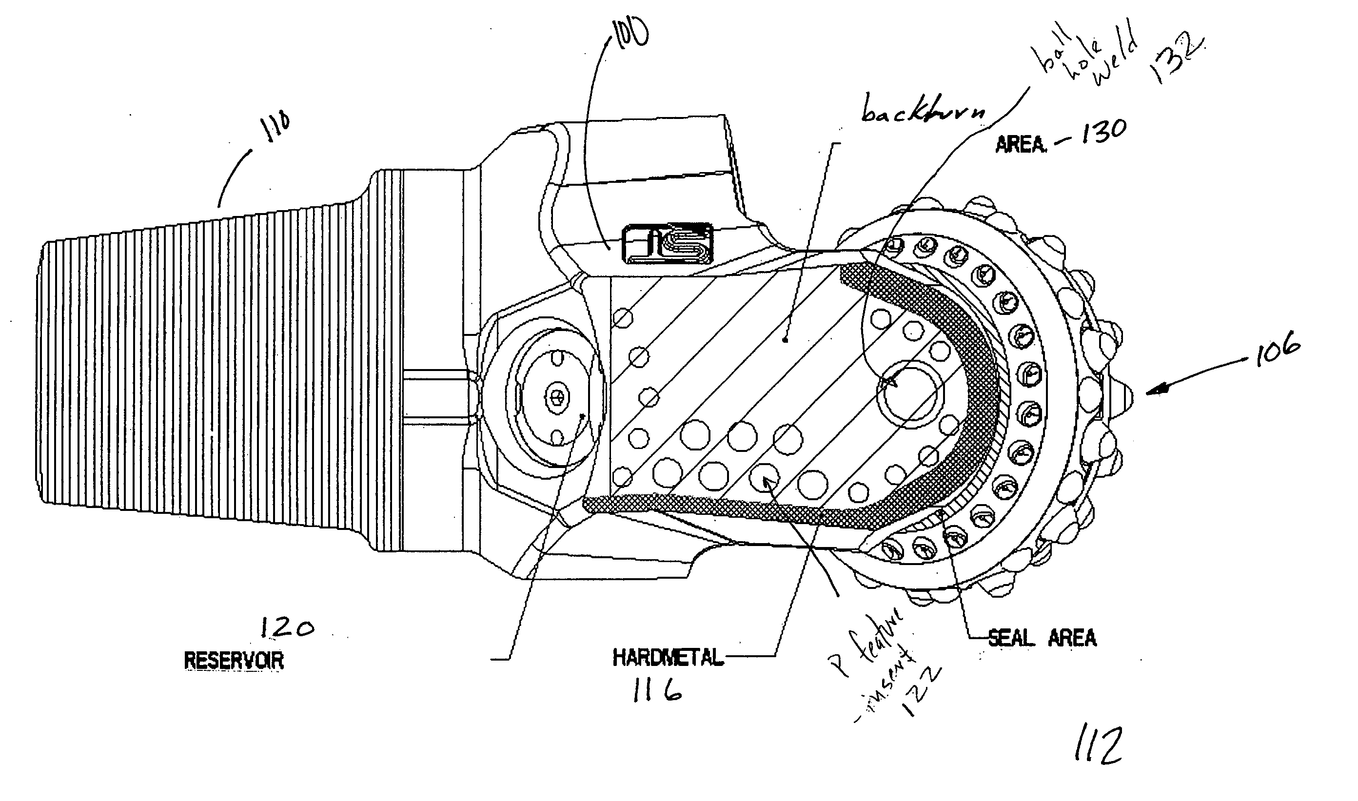
[0022] In one aspect, the present invention relates to a method for improving the durability of a roller cone bit. In another aspect, the present invention relates to a drill bit having improved durability when compared to prior art bit. In particular, the methods and bits of the present invention comprise treating at least a portion of a roller cone bit leg surface.

[0023] In one embodiment, the treating comprises inducing a residual compressive stress in a backturned surface of at least one roller cone drill bit leg. In one specific embodiment, inducing the residual stress comprises applying a shot peening process to the selected area (i.e., at least a portion of the leg backturn area). As those having ordinary skill in the art are aware, shot peening is a cold working process in which the surface of a part is bombarded with small spherical media called shot. Shot-peening is a controlled cold work process in which the surface of a part is bombarded with controlled impingement of a...


PUM

PropertyMeasurementUnit
Fractionaaaaaaaaaa
Lengthaaaaaaaaaa
Electric chargeaaaaaaaaaa

Abstract

The present invention relates to a roller cone drill bit that includes a bit body adapted to be rotated about a longitudinal axis, where the bit body has at least one leg depending therefrom, wherein the leg comprises a treated portion that provides a residual compressive stress, and a roller cone rotatably mounted on a journal. The treated portion treatment may comprise one selected from shot peening, laser-shock peening, and hammer peening. Further, the present invention relates to a method of manufacturing a roller cone drill bit that includes inducing a compressive stress, through plastic deformation, in at least a portion of at least one leg depending from a bit body. The inducing a compressive stress may comprise one selected from shot peening, laser-shock peening, and hammer peening.

Description

BACKGROUND OF INVENTION [0001] 1. Field of the Invention [0002] The invention is related generally to the field of roller cone drill bits. More particularly, the invention is related to methods for increasing the durability of a roller cone bit. [0003] 2. Background Art [0004] Drill bits used to drill wellbores through earth formations generally fall within one of two broad categories of bit structures. Shear cutter bits are configured with a multitude of cutting elements directly fixed to the bottom, also called the face, of the drill bit. The shear bit has no moving parts, and its cutters scrape or shear rock formation through the rotation of the drill bit by an attached drill string. Shear cutter bits have the advantage that the cutter is continuously in contact with the formation and see a relatively uniform loading when cutting the gage formation. [0005] Furthermore, the shear cutter is generally loaded in only one direction. This significantly simplifies the design of the shea...

Claims


Application Information

Patent Timeline
IPC IPC(8): E21B10/00E21B10/08
CPCE21B10/08B23K26/0069B23K26/356
Inventor BRAMLETT, KENNETHGRIFFO, ANTHONYLIANG, DAH-BENPOTTICARY, ADAM
Owner SMITH INT INC
Why Eureka
Try Eureka