Compressed gas cylinder safety device

a gas storage device and compressed gas technology, applied in the direction of operating means/releasing devices of valves, container discharging methods, liquid handling, etc., can solve the problems of compressed gas in paintball and other activities, presenting several safety hazards, and posing certain safety hazards

Inactive Publication Date: 2005-11-17
SMART PARTS +1
View PDF15 Cites 17 Cited by
  • Summary
  • Abstract
  • Description
  • Claims
  • Application Information

AI Technical Summary

Benefits of technology

[0016] The first threaded section of the valve stem is preferably threaded into the compressed gas cylinder so that the threaded section becomes arranged entirely within a central area of the cylinder and no longer engages the internal bottle threads. The second threaded section can then be threaded into the cylinder. Vents are preferably arranged at a position along the non-threaded section between the first and second threaded sections to vent compressed gas from the interior of the cylinder before the first threaded section can be removed from the cylinder. The first threaded section can be reverse threaded with respect to the second threaded section to ensure that the first threaded section cannot become accidentally removed from the cylinder. Reverse threading, loctite, and/or other connection methods can be employed between the on/off valve and the valve stem to prevent accidental removal of the on/off valve from the valve stem.
[0017] The safety device preferably p

Problems solved by technology

The use of compressed gases in paintball and other activities can present several safety hazards.
Compressed gas cylinders, for example, pose certain safety hazards simply because they contain gas under pressure.
Regardless of the properties of the gas, any gas under pressure can explode if the cylinder in which it is contained is improperly stored or handled.
Pressurization of a cylinder creates a potential hazard even for inert gases.
Failure of the cylinder and/or valve can therefore create an extremely dangerous projectile.
Specifically, rapid release of stored gases can cause the storage container to act as a projectile.
For this reason, improperly releasing the gas from a compressed gas cylinder is extremely dangerous.
Compressed gas storage cylinders, regardless of whether they are made of

Method used


Image

  • Compressed gas cylinder safety device
  • Compressed gas cylinder safety device
  • Compressed gas cylinder safety device

Examples


Embodiment Construction

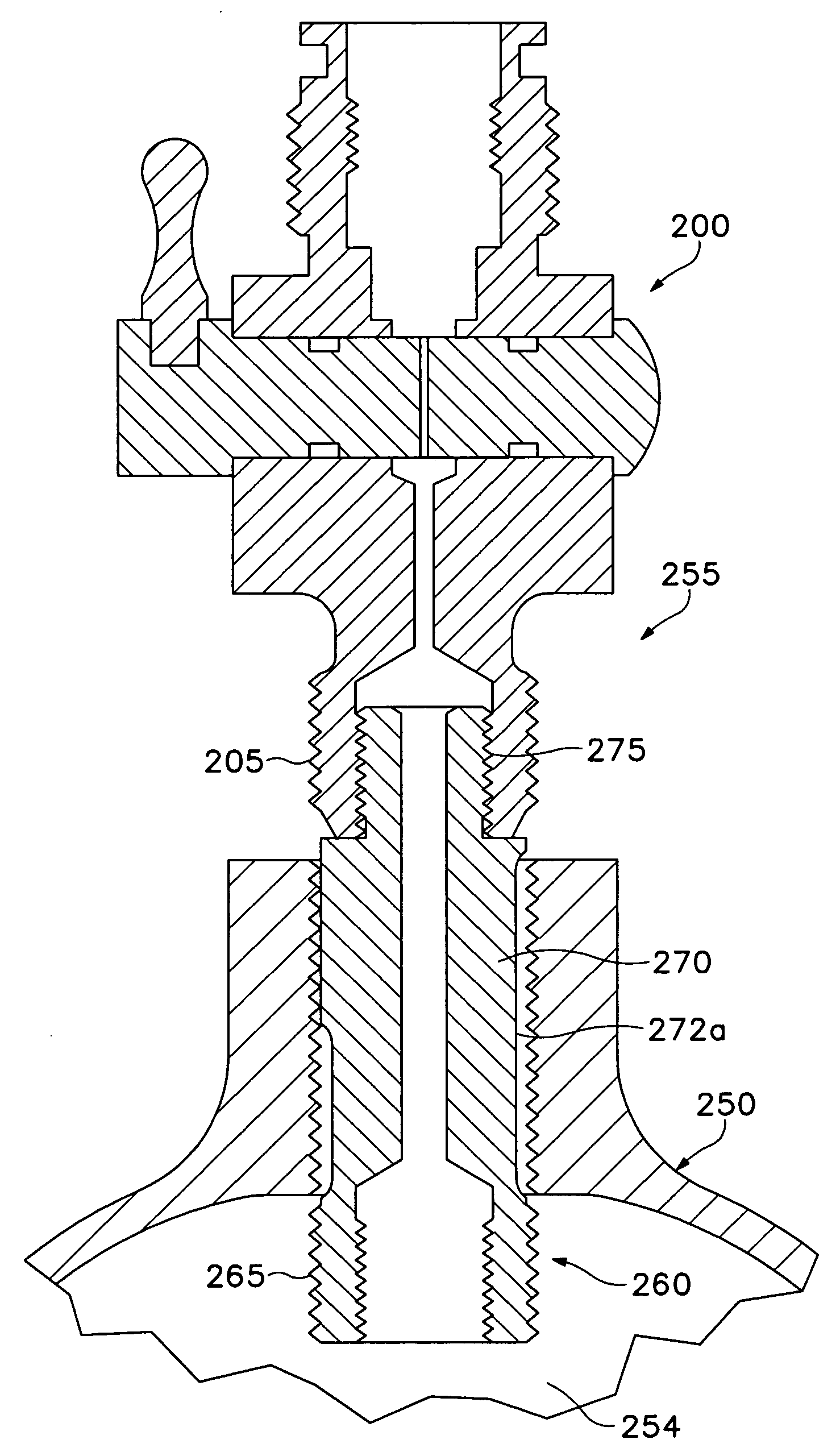
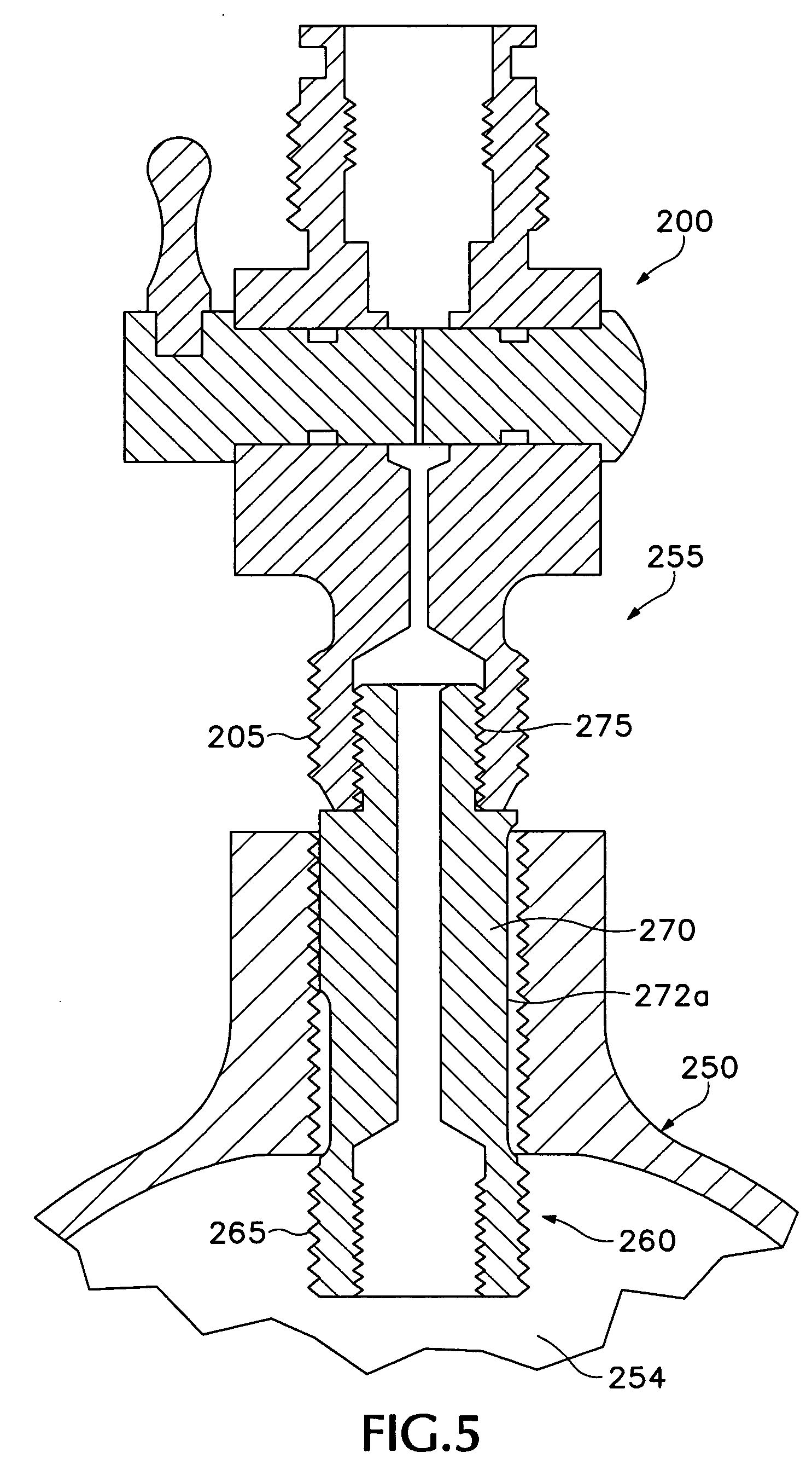
[0031] As identified above, the accompanying drawings show the construction of various preferred embodiments of the present inventive concepts. Referring first to FIG. 5, a valve safety device 255, according to one aspect of the present invention, preferably includes a valve stem 260 and an on / off valve assembly 200. The valve safety device 255 is shown with an on / off valve 200 connected to a compressed gas storage cylinder 250. In FIG. 5, the valve safety device 255 is shown in a partially removed position with respect to a compressed gas cylinder 250 in order to more fully illustrate various concepts of the present invention.

[0032] In other embodiments (not shown), the on / off valve can be omitted and the safety device can be constructed as a single piece with the bottle valve threads arranged on the exposed end of the safety device mating directly with a bottle receptacle on a paintball gun or other device configured to utilize compressed gas. The on / off valve could also be integ...


PUM


Abstract

An improved apparatus and method for preventing accidental disconnection of a valve fitting from a compressed gas cylinder (tank) is provided. A valve safety device preferably includes a valve stem having a first threaded section. The first threaded section is preferably configured to engage threads in an internal section of a compressed gas storage device during insertion and reside within an internal portion of the compressed gas storage device following insertion. A non-threaded section is preferably arranged proximal to the first threaded section. One or more vents are preferably provided on the non-threaded section to provide for a safe release of compressed gas from the compressed gas storage device before the first threaded section can be removed from the compressed gas storage device.

Description

[0001] This application claims priority from U.S. Provisional Patent Application Ser. No. 60 / 571,006, filed May 13, 2004, the contents of which are hereby incorporated herein by reference in their entirety.BACKGROUND OF THE INVENTION [0002] 1. Field of the Invention [0003] This invention relates generally to compressed gas storage devices. More particularly, however, this invention relates to methods and devices for safely connecting a release valve to the storage device. [0004] 2. Background Issues and Related Art [0005] The use of compressed gases in paintball and other activities can present several safety hazards. Compressed gas cylinders, for example, pose certain safety hazards simply because they contain gas under pressure. Regardless of the properties of the gas, any gas under pressure can explode if the cylinder in which it is contained is improperly stored or handled. Pressurization of a cylinder creates a potential hazard even for inert gases. A typical cylinder pressuriz...

Claims


Application Information

Patent Timeline
IPC IPC(8): F16K1/30F16K17/36F16K51/00F17B1/12F17B1/14F17C13/04
CPCF16K1/301F17C13/04F17C2201/0109F17C2201/058F17C2205/0332F17C2270/0745F17C2223/0123F17C2223/035F17C2260/042F17C2270/07F17C2270/0736F17C2205/0382
Inventor GARDNER,, WILLIAM JR.JONES, DANIAL S.
Owner SMART PARTS
Why Eureka
Try Eureka