Driving apparatus

Inactive Publication Date: 2005-11-17
KONICA MINOLTA OPTO
View PDF4 Cites 10 Cited by
  • Summary
  • Abstract
  • Description
  • Claims
  • Application Information

AI Technical Summary

Benefits of technology

[0013] The driving apparatus of the invention, in which the electromechanical transducer is bonded at one end to the fixed member and at the other end to the driving friction member, is used to move the movable unit mounted on the driving friction member by expansion and contraction of the electromechanical transducer. In the invention, the bonded surface of the electromechanical transducer to the driving friction member is included in, that is, smaller in area than the bonded surface of the driving friction member to the elec

Problems solved by technology

However, even the adhesive that crept very thinly would also interfere with the bearing 105.
Ho

Method used


Image

  • Driving apparatus
  • Driving apparatus
  • Driving apparatus

Examples


Embodiment Construction

[0021] A detailed description of a preferred embodiment of the present invention will now be given referring to the accompanying drawings. In the present embodiment, the invention is applied to a driving apparatus utilizing a piezoelectric element.

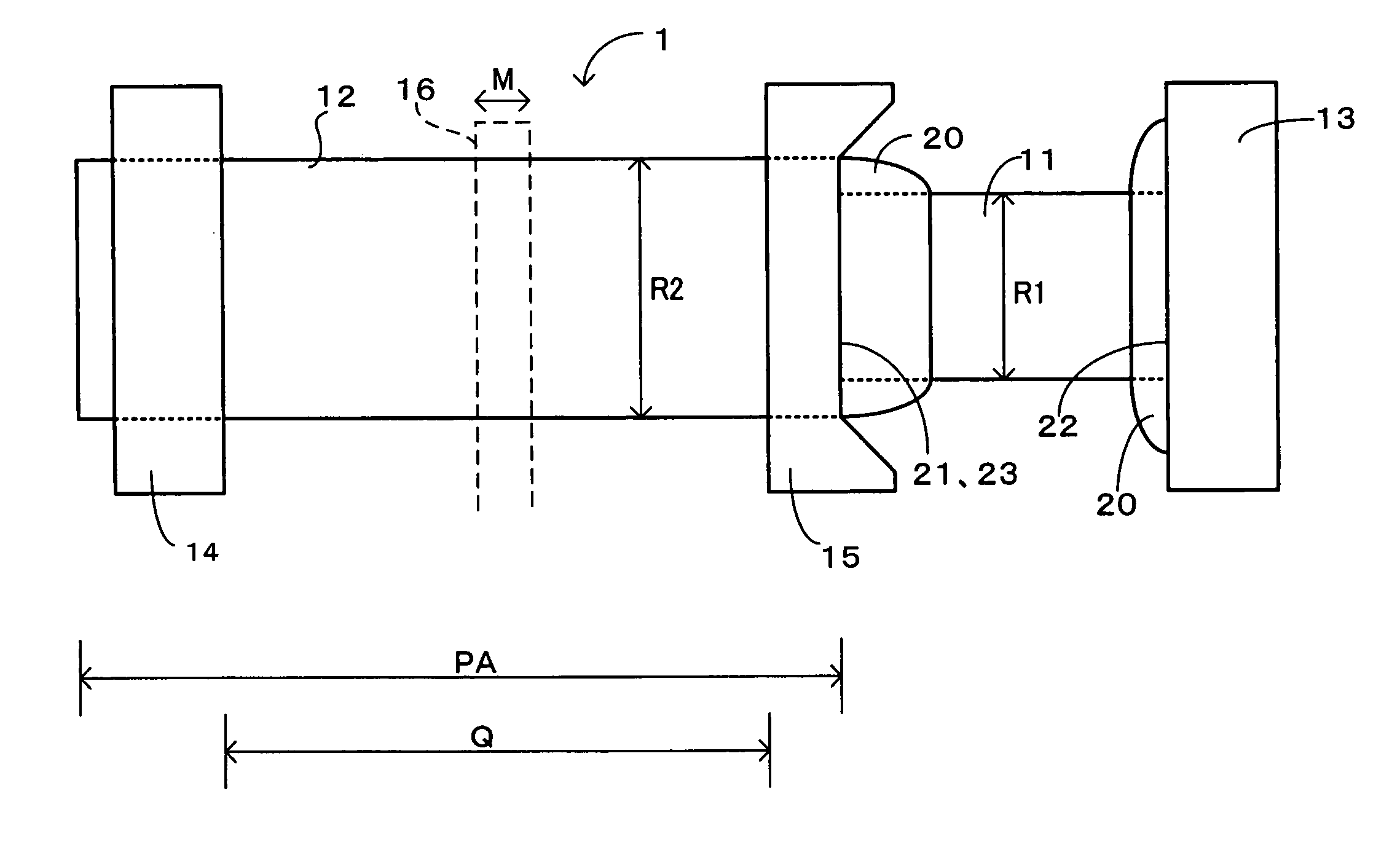
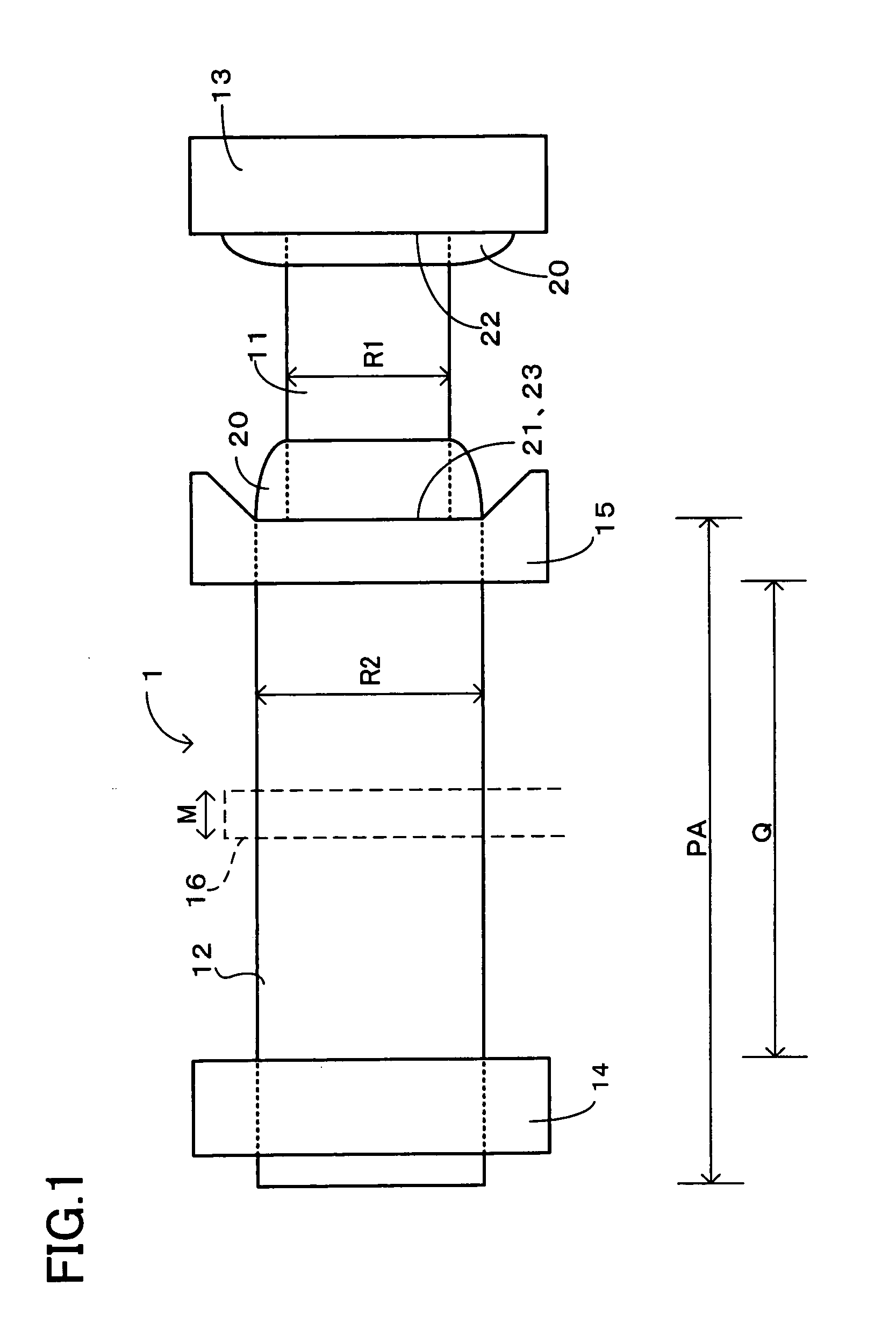
[0022] As shown in FIG. 1, a driving apparatus 1 in the present embodiment is constructed such that a piezoelectric element 11 is adhered and fixed at one end to a driving friction member 12 and at the other end to a fixed member 13. Arranged at both ends of the driving friction member 12 are bearings 14 and 15 which hold the driving friction member 12 movably in its axial direction. A movable unit 16 is slidably engaged on the driving friction member 12 between the bearings 14 and 15 with friction. This driving apparatus 1 is used to move the movable unit 16 in the axial direction indicated by an arrow M.

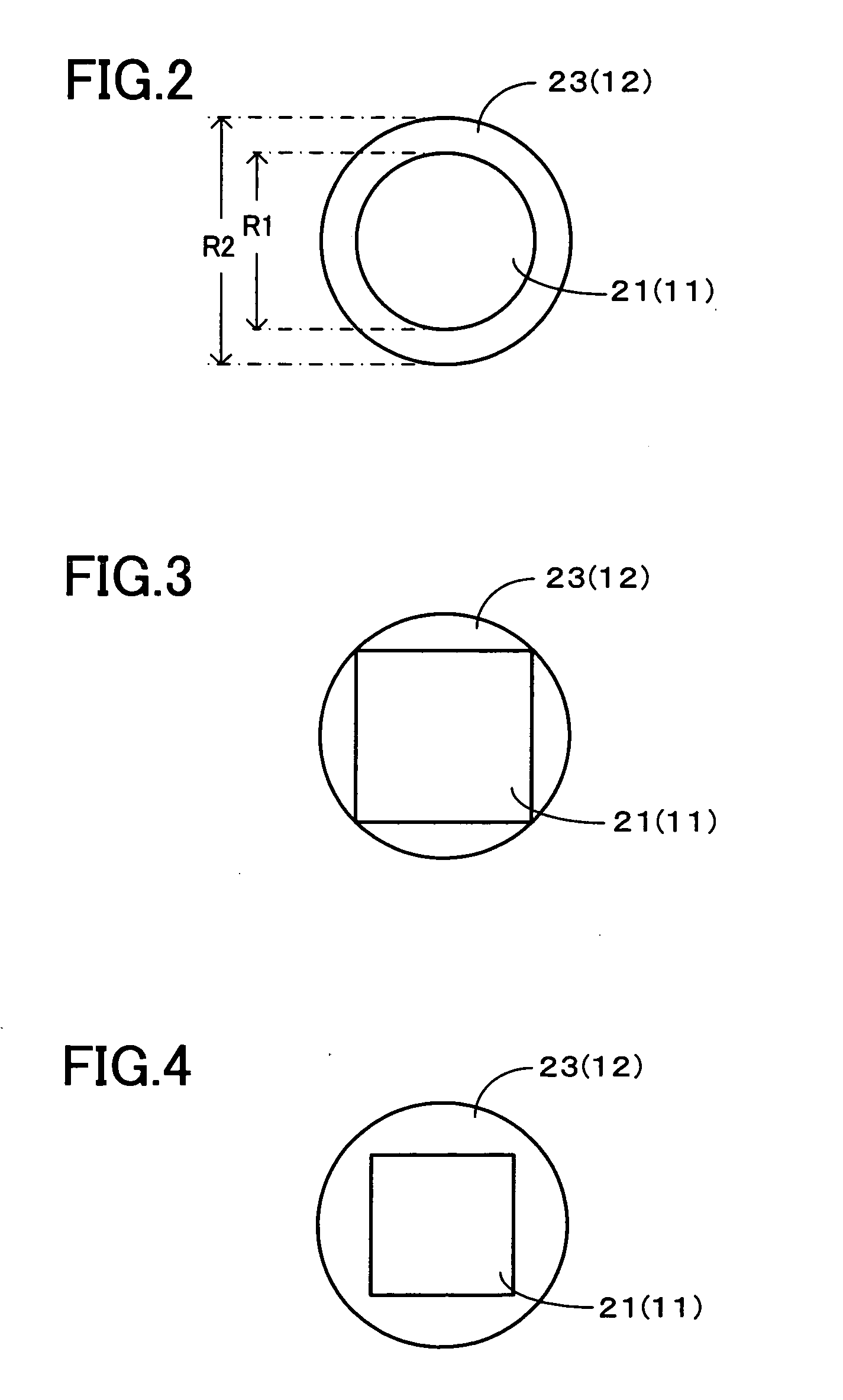
[0023] In this driving apparatus 1, the driving friction member 12 is of a cylindrical shape having a diameter R2 determined to be sli...


PUM


Abstract

A driving apparatus of the invention comprises a fixed member, a piezoelectric element fixed at one end to the fixed member, and a driving friction member fixed to the other end of the piezoelectric element. The driving apparatus of the invention is arranged to move a movable unit which is slidably mounted on the driving friction member by expansion and contraction of the piezoelectric element. Herein, a bonded surface of the piezoelectric element to the driving friction member is included in a bonded surface of the driving friction member to the piezoelectric element.

Description

CROSS-REFERENCE TO RELATED APPLICATIONS [0001] This application is based upon and claims the benefit of priority from the prior Japanese Patent Application No. 2004-144586 filed on May 14, 2004, the entire contents of which are incorporated herein by reference. BACKGROUND OF THE INVENTION [0002] 1. Field of the Invention [0003] The present invention relates to a driving apparatus using an electromechanical transducer such as a piezoelectric element, an electrostrictive element, or a magnetostrictive element. More particularly, the present invention relates to a driving apparatus in which a driving friction member is bonded to an electromechanical transducer by adhesive. [0004] 2. Description of Related Art [0005] Heretofore, there has been used a driving apparatus for moving a movable unit by utilizing an electromechanical transducer such as a piezoelectric element, an electrostrictive element, or a magnetostrictive element. In such driving apparatus, for example, the electromechani...

Claims


Application Information

Patent Timeline
IPC IPC(8): H02N2/00H01L41/08H01L41/09
CPCH02N2/025
Inventor OKAMOTO, YASUHIRO
Owner KONICA MINOLTA OPTO
Why Eureka
Try Eureka