Method, apparatus and article for vibration compensation in electric drivetrains

Inactive Publication Date: 2005-11-17
CONTINENTAL AUTOMOTIVE SYST INC
View PDF49 Cites 17 Cited by
  • Summary
  • Abstract
  • Description
  • Claims
  • Application Information

AI Technical Summary

Benefits of technology

[0008] In one embodiment, a peak level detector determines a peak of vibration, and a corresponding compensation value which is subtracted from a limited commanded

Problems solved by technology

However, simple transmissions may be subject to “backlash” where the mating teeth of two gears (e.g., a driving gear and a driven gear) are not in contact when the driving gear begins to move.
The result may produce a significant impact between the teeth of the gears, creating excess forces and consequently wear on the teeth of the gear.
The impact may also introduce a significant tors

Method used


Image

  • Method, apparatus and article for vibration compensation in electric drivetrains
  • Method, apparatus and article for vibration compensation in electric drivetrains
  • Method, apparatus and article for vibration compensation in electric drivetrains

Examples


first embodiment

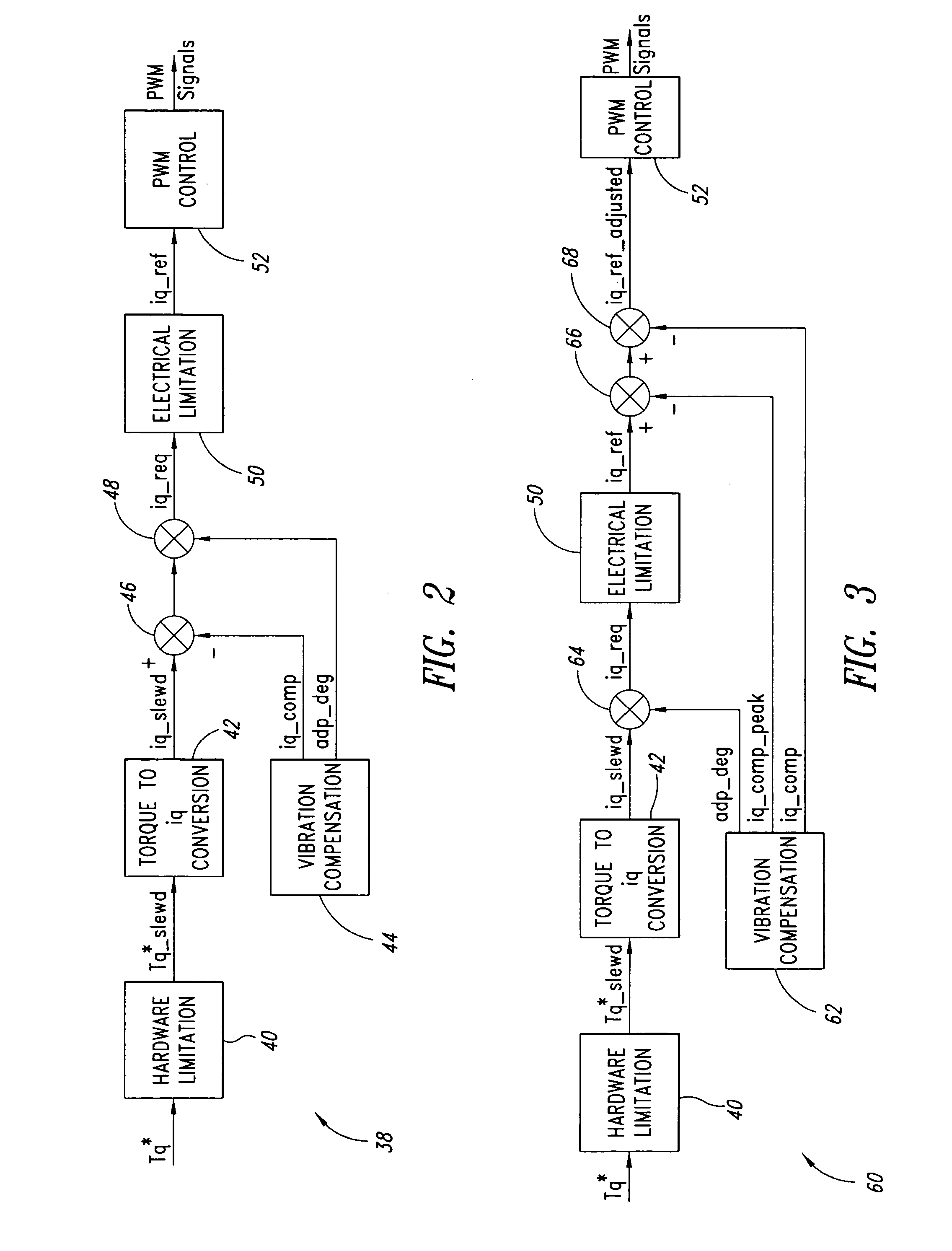
[0055] In a first embodiment, the peak detection function is performed as part of the vibration compensation function 62 according to the following algorithm:

if |iq—comp(n)|>peak(n−1) then

peak(n)=|iq—comp(n)|

else

peak(n)=peak(n−1)−K*peak(n−1), [0056] where n is an integer value representing successive samples; and where K is a constant with the property 0

[0057] Thus, in the first embodiment the peak detection function sets the present peak value equal to the absolute value of the present torque current compensation value iq—comp where the absolute value of the present torque current compensation value iq—comp is greater than the previous peak value. Otherwise the peak detection function sets the present peak value equal to the previous peak value minus a percentage of the previous peak value, where the percentage is defined by the constant K. The constant K sets the slope of the function.

second embodiment

[0058] Since the absolute value of the torque current compensation value iq—comp is used in the above approach, there is a decrease in the torque current reference iq—ref if there is a big negative peak in the torque current compensation value iq—comp, whereas there is no impact with respect to battery limitation. In at least some embodiments, it may be desirable to have the peak detection function work for both for a positive peak if the torque current reference iq—ref is a positive value, and for a negative peak if the torque current reference iq—ref is negative value. the peak detection function achieves this by calculating separate values, maximum torque current compensation value iq—comp—max and minimum torque current compensation value iq—comp—min for positive and negative compensation, respectively, where the torque current reference iq—ref is given by equation 1, below.

iq—ref=iq—battery—limited−[(iq—ref>0)*iq—comp—max+(iq—refiq—comp—min]+iq—comp  Equation 1

[0059] The second...


PUM


Abstract

A torque current peak compensation value is subtracted from a torque current reference value, where the torque current peak compensation value is based at least in part on a determined peak of vibration. A torque current compensation value is subtracted from the results to produce an adjusted torque current reference value.

Description

BACKGROUND OF THE INVENTION [0001] 1. Field of the Invention [0002] The disclosure is generally related to electric drivetrains, and particularly to electric drivetrains comprising an alternating current (AC) electric motor powered by a direct current (DC) power source via one or more inverters. [0003] 2. Description of the Related Art [0004] In contrast to an internal combustion engine, an electric motor can operate over a very wide range of rotational speeds. Thus, a multiple-speed transmission is not required in a vehicle propelled by an electric motor (e.g., electric vehicle or hybrid vehicle), as is the case for an internal combustion engine in order to convert the relatively narrow speed range of an internal combustion engine to a wider range of vehicle speeds. Consequently, electrically propelled vehicles may employ simple transmissions, for example, single-speed transmissions. [0005] A simple transmission has several benefits, including reduced number of parts, reliability a...

Claims


Application Information

Patent Timeline
IPC IPC(8): H02P7/00H02P21/05
CPCH02P21/05
Inventor SOUDIER, CHRISTOPHEHAMPO, RICHARD J.REDDY, VINODNALLAPA, VENKATAPATHI R.
Owner CONTINENTAL AUTOMOTIVE SYST INC
Why Eureka
Try Eureka