
Radio communication system, radio communication device, and radio communication method

a radio communication system and radio communication technology, applied in the field of radio communication systems, can solve the problems of difficult to increase the transmission distance, difficult to increase the speed, and great adverse effect on the operation of the quadrature demodulation unit, and achieve the effect of suitably performing data communication

Inactive Publication Date: 2005-11-17
SONY CORP
View PDF5 Cites 45 Cited by
  • Summary
  • Abstract
  • Description
  • Claims
  • Application Information

AI Technical Summary

Benefits of technology

[0040] It is desirable to provide a radio communication system, a radio communication device, and a radio communication method that are excellent in suitably performing data communication by a backscatter system using transmission of an unmodulated carrier from a reading device side, and absorption and reflection of the received radio wave on the basis of an operation of terminating an antenna on a transmitting device side.
[0041] It is also desirable to provide a radio communication system, a radio communication device, and a radio communication method that are excellent in eliminating effects of transmitter noise on the reading device side to improve reception sensitivity and increase the communication distance.
[0042] It is also desirable to provide a radio communication system, a radio communication device, and a radio communication method that are excellent in eliminating the effects of a DC offset and transmitter noise on the tag reader side to improve the reception sensitivity and increase the communication distance by shifting an unmodulated carrier of frequency fO from the tag reader side by fS on the tag side and returning a reflected wave.

Problems solved by technology

That is, the receiving unit is easily affected by a DC offset and transmitter noise, thus making it difficult to increase the transmission distance.
In addition, a modulation system in the backscatter system is generally an ASK modulation system or a PSK modulation system in most cases, thus making it difficult to increase speed.
This forms a DC offset, which produces a great adverse effect on operation of the quadrature demodulation unit 515.
Thus, the very small modulated signal becomes distorted and difficult to demodulate, thereby constituting a major impediment to increasing the transmission distance.
However, a loss from insertion of the band-pass filter 106 occurs twice, causing a decrease in reflection efficiency.
In addition, the insertion of the band-pass filter 106 increases the device cost.
However, the above-described method of shifting the unmodulated carrier of the frequency fO from the tag reader side by fS on the tag side and returning the reflected wave has the following problems.
However, when the filter is used in the backscatter system, a loss from the insertion of the filter occurs in both directions, causing a decrease in reflection efficiency.
In addition, an increase in the cost of the filter is a problem.
Thus, when only one side is used, the energy allocated to the unused other side constitutes a power loss, thus causing a decrease in the power of the reflected wave.
The backscatter system using ASK causes a greater decrease in the power.
That is, the level of the originally very weak reflected wave is further lowered, which is one cause of the decrease in communication distance.

Method used


Image

  • Radio communication system, radio communication device, and radio communication method
  • Radio communication system, radio communication device, and radio communication method
  • Radio communication system, radio communication device, and radio communication method

Examples


Embodiment Construction

[0068] Preferred embodiments of the present invention will hereinafter be described in detail with reference to the drawings.

[0069] The present invention relates to an RFID system in which a tag can perform data communication without a power supply by a backscatter system.

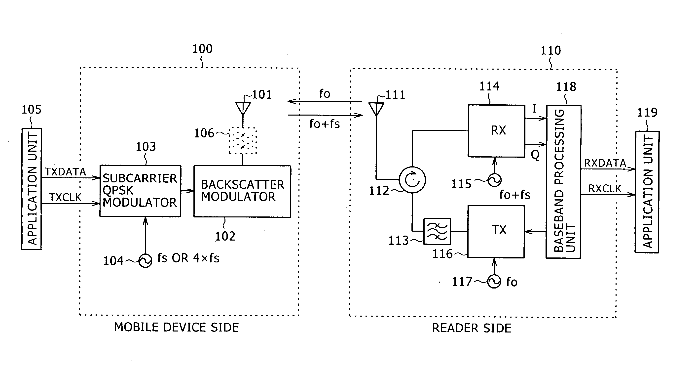
[0070] In an ordinary RFID system, the frequency of a carrier from a reader and the center frequency of a reflected wave are the same, and since the reader side performs transmission and reception at the same frequency, a receiving unit of the tag reader is affected by a DC offset and transmitter noise.

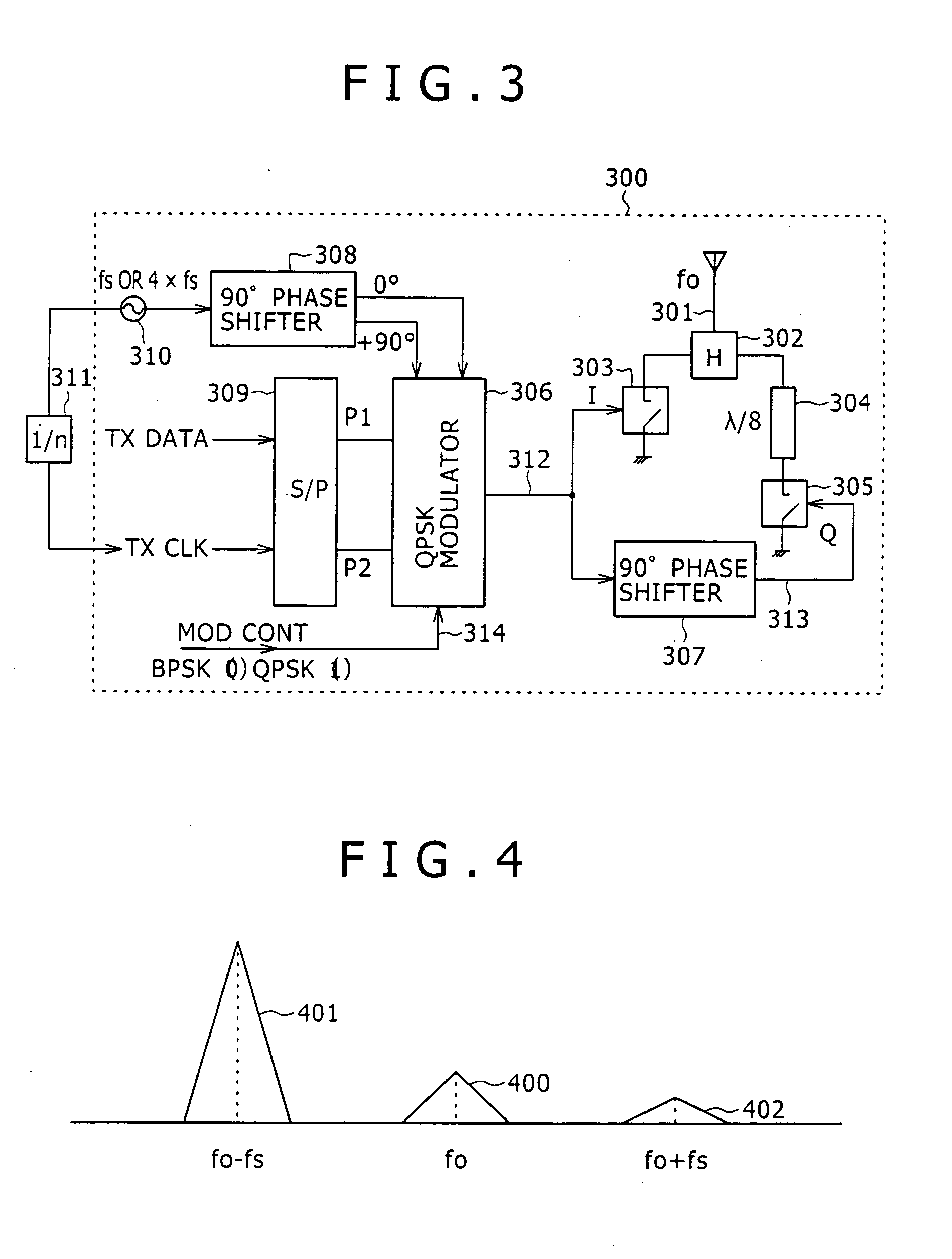
[0071] On the other hand, a radio communication system according to an embodiment of the present invention eliminates the effects of a DC offset and transmitter noise on a tag reader side by shifting an unmodulated carrier of a frequency fO from the tag reader side by fS on a tag side and then returning a reflected wave.

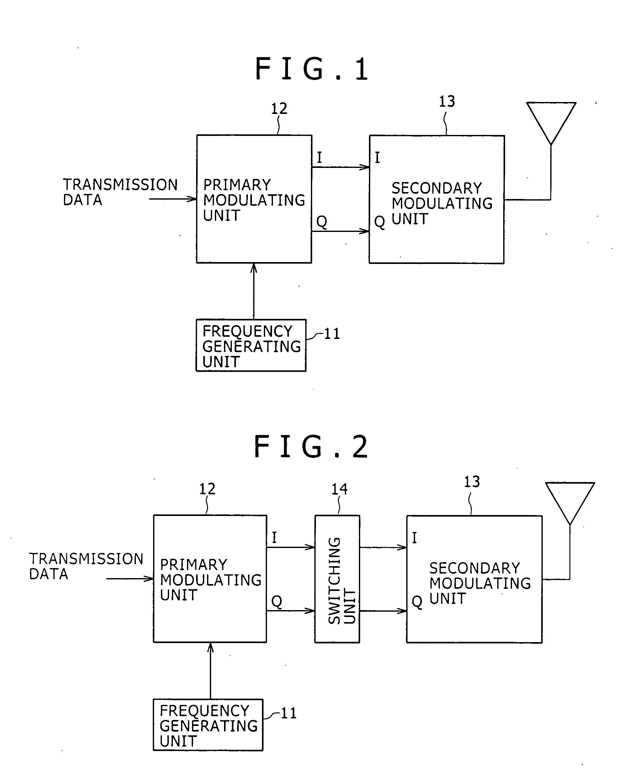
[0072]FIG. 1 schematically shows the configuration of a radio communication device 10 accordin...


PUM


Abstract

A radio communication system performs data communication by a backscatter system using absorption and reflection of a received radio wave. In the system, a data reading device transmits an unmodulated carrier of frequency fO; a data transmitting device subjects transmission data to primary modulation using a center frequency fS to obtain a primary modulated signal, and subjects the primary modulated signal to secondary modulation by multiplying the primary modulated signal by an input of the unmodulated carrier of the backscatter system to generate a reflected modulated wave in which one of frequencies fO+fS and fO−fS is suppressed; and the data reading device receives the reflected modulated wave from the data transmitting device.

Description

CROSS-REFERENCE TO RELATED APPLICATIONS [0001] The present application claims priority from Japanese Application No. 2004-140580 filed May 11, 2004, the disclosure of which is hereby incorporated by reference herein. BACKGROUND OF THE INVENTION [0002] The present invention relates to a radio communication system, a radio communication device, and a radio communication method using microwaves in a specific frequency band, and particularly to a radio communication system, a radio communication device, and a radio communication method for realizing communication operation with low power consumption between devices at a relatively short distance. More particularly, the present invention relates to a radio communication system, a radio communication device, and a radio communication method that perform data communication by a backscatter system using transmission of an unmodulated carrier from a reading device side, and absorption and reflection of the received radio wave on the basis of...

Claims


Application Information

Patent Timeline
Patent Type & Authority Applications(United States)
IPC IPC(8): G01S13/75G06K7/00G06K17/00G06K19/07G08C17/02H03D1/00H04B1/00H04B1/59H04B5/02H04L5/14H04L27/00
CPCG01S13/758H04L5/143G06K19/0723G06K7/0008F16L21/065F16L25/0036
Inventor FUKUDA, KUNIO
Owner SONY CORP
Learn More